
Method for manufacturing injection product model

A technology for injection molding products and manufacturing methods, which is applied in the field of precision integrated injection molding product model production based on fitting and positioning anti-deformation processing, which can solve problems such as inaccurate positions, difficult data point processing, and easy deformation of products, so as to improve product manufacturing speed , shorten the product handover time, improve the effect of product quality

Active Publication Date: 2013-10-09
XINYI AUTOMOBILE GLASS (SHENZHEN) CO LTD
View PDF5 Cites 11 Cited by
  • Summary
  • Abstract
  • Description
  • Claims
  • Application Information

AI Technical Summary

Problems solved by technology

[0004] At present, in the reverse design of products such as sunroofs, side windows, front windows, and tail windows that are integrally molded, it is necessary to pay attention to multiple links, such as the Santa Fe triangle window, DW1191 and other complex product designs. 3D laser scanning first, because there are many features and curved surfaces, the difficulty is how to scan and fit the point cloud, and how to design a complete and qualified digital model with millions of points through reverse thinking, such as this kind of products, especially It is the edge, because the wall is thin, the material is soft, the product is easy to deform and twist, the reference is difficult to find, the position of the closed point cloud is not accurate, and the data point processing is difficult. In the subsequent design process, it is completely in accordance with the denatured product. The data points are designed, the surface is not smooth, the appearance of the product is not good, and there will be distortion when reflecting light, but after the edge is adjusted and smoothed locally, the size cannot be controlled, and the length of the edge of the injection molded product is different

Method used


Image

  • Method for manufacturing injection product model
  • Method for manufacturing injection product model

Examples


Embodiment Construction

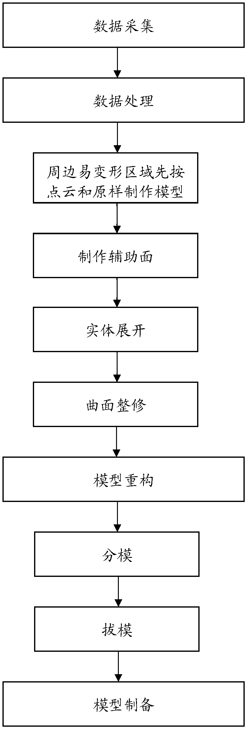
[0022] Such as figure 1 As shown, the integrated injection molding product design method of the present invention includes the following steps:

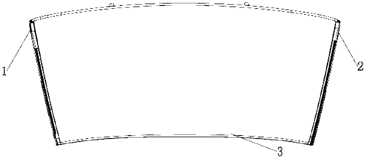
[0023] (1) Data acquisition, including scanning of samples, for the deep and narrow part of the groove, it is first bent to deformation and then three-coordinate laser scanning, firstly uses three-point positioning in space to find the reference, and then scans the front and back lasers and collects data; the three-point positioning Finding the reference is to stick three balls anywhere around the product before laser scanning, and then laser scan the front and back of the product including the glued balls; the reference is the center point of the three balls; The benchmark error is controlled at 0.005-0.01.

[0024] (2) Data processing, for the deformable area around the product, follow the steps below:

[0025] 1) Corresponding to the easily deformable area around the product, the original point cloud model is obtained by laser s...


PUM


Abstract

The invention discloses a method for manufacturing an integrated injection product model. The method comprises the following steps of: (1) acquiring data, (2) processing the data, (3) reconstructing the model, and (4) manufacturing the model. The step (1) comprises the substeps of breaking off deep and shallow parts of a groove until the groove is deformed and then acquiring the data; the step (2) is used for treating an easily deforming region around the product in the following way: 1) manufacturing an original shape point cloud model on a deforming part of a soft edge of the periphery according to an original shape, 2) then producing an auxiliary surface, 3) unfolding an entity, and 4) finishing a curved surface and fitting scanning points on the break-off deforming parts; the step (3) comprises the following substeps: splitting the product model, then properly dragging the model until a final counter-deformation model of an integrated injection product meeting a precision requirement is obtained and eventually obtaining the product entity model according to the final counter-deformation model. According to the method, the model manufacturing cost can be reduced, the product manufacturing speed can be increased, the product handover time is shortened, and the product quality is improved.

Description

technical field [0001] The invention relates to a method for making a model of an integral injection molding product, in particular to a method for making a model of a precision integral injection molding product based on fitting and positioning anti-deformation processing. Background technique [0002] With the rapid development of economy and technology, product design is applied in all aspects of production and life at the same time. The forward design process is a process from scratch. The designer first conceives the shape, performance, strength and practical performance of the product, and then uses hand-drawn sketches or computer graphics to the original clay and plaster modeling. It is a slow production process and the final product is completed. Forward design of products; reverse engineering technology refers to the process of measuring the real object or model with a certain measurement method, and reconstructing the CAD 3D model of the real object through the thr...

Claims


Application Information

Patent Timeline
IPC IPC(8): B29C33/38
Inventor 李圣根
Owner XINYI AUTOMOBILE GLASS (SHENZHEN) CO LTD
Learn More