
Printing paper air-suction flattening device

A technology for printing paper and flattening device, which is used in transportation and packaging, thin material handling, and sending objects, etc. It can solve the problems of inability to flatten, not applicable, and can only be used in offline detection, and achieve the effect of ensuring flattening. , to avoid the effect of image distortion

Active Publication Date: 2013-10-09
CHENGDU BANKNOTE PRINTING +1
View PDF5 Cites 6 Cited by
  • Summary
  • Abstract
  • Description
  • Claims
  • Application Information

AI Technical Summary

Problems solved by technology

[0004] The existing printing defect detection effect is better to use the roller to press the cardboard, which can eliminate the stretching deformation and the distortion deformation, but this method must be in contact with both sides of the paper, and can only be used on the roller structure. It can be used for offline detection, but it is not suitable for real-time online detection just after printing
The second is to add air blowing to the cylinder, but the blowing effect is not good for eliminating the extension and deformation caused by embossing, especially if the paper edge is warped, the air blowing cannot flatten it, and most of them are used on solid cylinders with low detection accuracy. , it is not applicable in the position where there is no supporting paper such as hollow drum or chain road

Method used


Image

  • Printing paper air-suction flattening device
  • Printing paper air-suction flattening device
  • Printing paper air-suction flattening device

Examples


Embodiment Construction

[0023] Below in conjunction with accompanying drawing, the present invention is described in detail.

[0024] In order to make the object, technical solution and advantages of the present invention clearer, the present invention will be further described in detail below in conjunction with the accompanying drawings and embodiments. It should be understood that the specific embodiments described here are only used to explain the present invention, not to limit the present invention.

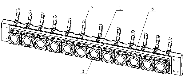
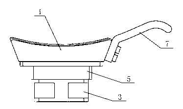
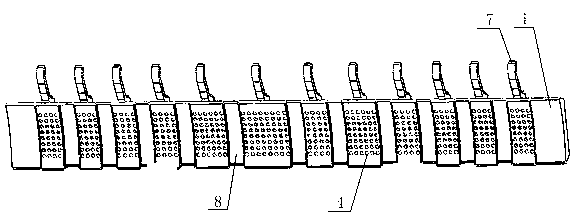
[0025] Such as Figure 7 and 8 As shown, a printing paper suction and flattening device includes a suction plate 1, a bonding plate 5 and a suction fan group, and the suction plate 1 is arranged on the outer periphery of the paper transfer roller 2 and corresponds to the paper transfer roller 2 The surface is a matching arc surface, and there is a gap for paper passing between the air suction plate 1 and the paper transfer roller 2. The air suction fan group is composed of several air suction fa...


PUM


Abstract

The invention discloses a printing paper air-suction flattening device. The printing paper air-suction flattening device comprises an air-suction plate and an air-suction fan set. The air-suction plate is arranged on the periphery of a paper conveying roller, and one face, corresponding to the paper conveying roller, of the air-suction plate is an arc face matched with the paper conveying roller. A gap which allows paper to pass through is reserved between the air-suction plate and the paper conveying roller. The air-suction fan set is composed of a plurality of air-suction fans which are arranged on the backside of the air-suction plate. Air-suction holes which correspond to the air-suction fans are formed in the arc surface of the air-suction plate. Compared with the prior art, the printing paper air-suction flattening device does not need to make simultaneous contact with the two sides of the paper, guarantees that the quality of the printing paper is not influenced, and is suitable for online inspection; in addition, the printing paper air-suction flattening device is provided with a unique mechanical structure, flattens the printing paper before an inspection point, enables the paper to fit in with an ideal path line all the time when the paper passes through the inspection point and avoids deformation of an image. Meanwhile, a paper strip upper supporting device and a paper strip lower supporting device ensure that a printing product moves according to a path of a chain way in other areas besides the air-suction plate, and therefore the effect of flattening of the printing paper is further ensured.

Description

technical field [0001] The invention relates to the field of printing quality detection, in particular to an air suction and flattening device for printing paper. Background technique [0002] With the development of computer science, machine vision technology has played an increasingly important role in the printing industry as a new quality control method. The real-time printing inspection system uses machine vision as the core technology, which can effectively monitor and control the production process of printed products. [0003] Real-time printing defect detection is carried out on the printing machine. After the printing is completed, in order to avoid the newly printed area during the delivery process, the cylinder is made hollow and transported by chains. In such a transmission mode, the paper will move in a free state due to the lack of the support of the roller, so it will show different degrees of stretching or twisting deformation at different machine speeds. T...

Claims


Application Information

Patent Timeline
IPC IPC(8): B65H29/52
Inventor 刘莘张宪汪雄刘天亮谢清松孙晓刚林敏夏小东
Owner CHENGDU BANKNOTE PRINTING
Learn More