Method for utilizing clean energy to extract freshwater from air and freshwater extracting device
What is Al technical title?
Al technical title is built by PatSnap Al team. It summarizes the technical point description of the patent document.
A clean energy and fresh water technology, applied in drinking water installations, water supply installations, buildings, etc., to solve drinking water problems and save energy
Inactive Publication Date: 2013-10-09
北京海德能水处理设备制造有限公司
View PDF5 Cites 5 Cited by
Summary
Abstract
Description
Claims
Application Information
AI Technical Summary
This helps you quickly interpret patents by identifying the three key elements:
Problems solved by technology
Method used
Benefits of technology
Problems solved by technology
[0005] How to use the huge energy contained in the temperature difference of seawater to extract fresh water from the air has not yet been studied in depth
Method used
Image
Click on the blue label to locate the original text in one second.
Reading with bidirectional positioning of images and text.
Examples
Embodiment 1
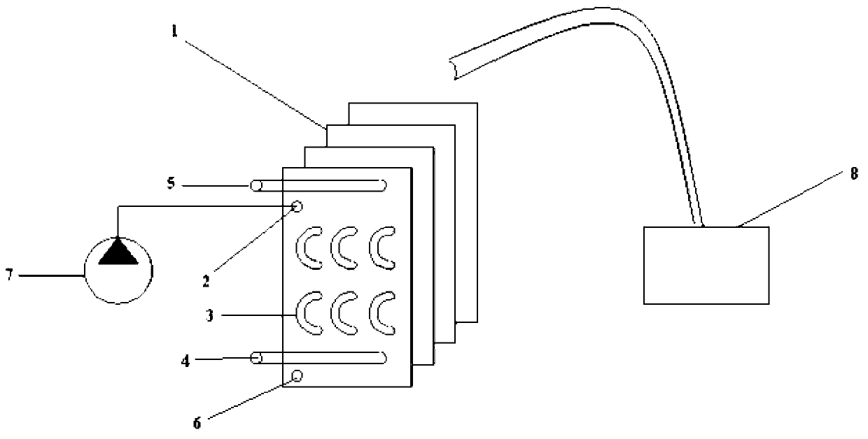
[0046] Fresh water extracting device of the present invention, specific structure sees image 3 , including wind driven plunger pump (7), moist air input device (8), coil-fin condenser, upper sump (5) and lower sump (6);
[0047] The water outlet of the wind driven plunger pump (7) is connected to the water inlet (2) of the condensing device;
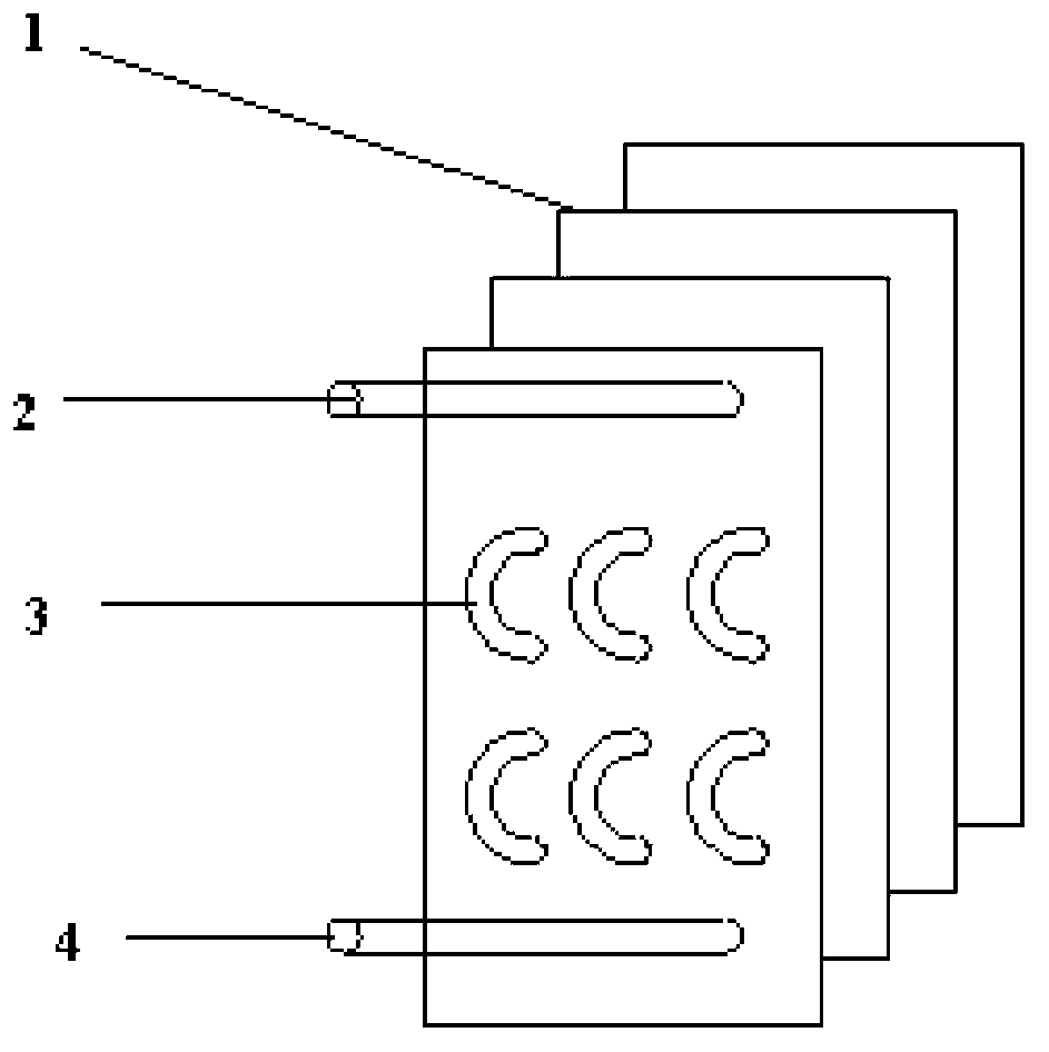
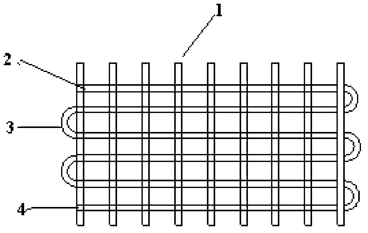
[0048] The coil-fin condenser includes sleeve fins (1) and serpentine coils (3);
[0049] The upper sump (5) and the lower sump (6) are respectively arranged at the upper and lower ends of the condensation device; the cross-sectional areas of the upper sump and the lower sump are both greater than or equal to the cross-sectional area of the condensation device.
[0050] Figure 4 It is a schematic diagram of the side structure of the condensing device and the fresh water collecting device in the fresh water extraction device, Figure 4 Among them, (1) is the sleeve fin, (2) is the water inlet pipe, (3) is the serpentine coil, (4) i...
Embodiment 2
[0053] Fresh water extracting device of the present invention, specific structure sees Figure 5 , Figure 5 It is a structural schematic diagram of the fresh water extraction device of Example 2, including a manual plunger pump (7), a humid air input device (8), a coil-fin condenser and a closed outer cover (9);
[0054] The water outlet of the manual plunger pump (7) is connected to the water inlet (2) of the coil-fin condenser;
[0055] The coil-fin condenser includes sleeve fins (1) and serpentine coils (3);
[0056] The outer cover includes an air input port (10) and an air output port (11), and the outer cover wraps the outside of the coil fin condenser; the moist air input device (8) connects with the air input port (10) The outer cover (9) communicates.
[0057] The humid air input device (8) inputs air with a humidity greater than 50% into the outer cover (9), and the manual plunger pump (7) inputs seawater at a depth of 50 meters to the serpentine plate of the con...
PUM
Abstract
The invention provides a method for utilizing clean energy to extract freshwater from air. The method comprises the steps of utilizing a drive plunger pump to input seawater with a depth larger than 50 meters to a condensing device, filling air with humidity larger than 50% in the surface of the condensing device, and obtaining the freshwater on the surface of the condensing device. The invention further provides a freshwater extracting device which comprises the drive plunger pump, a humid air input device, the condensing device and a freshwater collecting device. The water outlet of the drive plunger pump is connected with the water inlet of the condensing device. The air output mouth of the humid air input device is communicated with the surface of the condensing device. The freshwater collecting device is in contact connection with the surface of the condensing device. According to the method for utilizing the clean energy to extract the freshwater from the air and the freshwater extracting device, a water pump is used for continuously leading the low-temperature seawater into the condensing device, cold energy enables water vapor in the air to be condensed and separated out, and therefore the freshwater is extracted. Therefore, the drive plunger pump which dose not consume electricity, coal, oil, liquefied gas and other conventional energy resources is adopted, the cold energy is fully utilized, energy resources are saved, and simplicity and practicality are achieved.
Description
technical field [0001] The invention relates to the field of fresh water extraction, in particular to a method and a fresh water extraction device for extracting fresh water from air by using clean energy. Background technique [0002] The atmosphere contains about 13 trillion m 3 The amount of water in China is more than six times that of all rivers and rivers around the world, about 2% of which has become water droplets in clouds, and the remaining 98% is still in the state of water vapor. Especially the air in coastal areas, islands, seas and coasts is very humid, with high moisture content and low salt content. [0003] Humid air is a mixture of dry air and water vapor. When the humid air is cooled, if the humid air is in an unsaturated state, its moisture content will not change, the temperature will drop, and the cooling process of unsaturated humid air will extend to a certain moisture content As the temperature decreases, the relative humidity increases. If the hu...
Claims
Application Information
Patent Timeline
Application Date:The date an application was filed.
Publication Date:The date a patent or application was officially published.
First Publication Date:The earliest publication date of a patent with the same application number.
Issue Date:Publication date of the patent grant document.
PCT Entry Date:The Entry date of PCT National Phase.
Estimated Expiry Date:The statutory expiry date of a patent right according to the Patent Law, and it is the longest term of protection that the patent right can achieve without the termination of the patent right due to other reasons(Term extension factor has been taken into account ).
Invalid Date:Actual expiry date is based on effective date or publication date of legal transaction data of invalid patent.