High voltage transmission conductor sag measuring device and method

A measurement device and wire sag technology, which is applied to measurement devices, electrical devices, electromagnetic means, etc., can solve problems such as many measurement parameters, low sag accuracy, and the safety of life and property of measurement workers. The effect of safe operation

Inactive Publication Date: 2013-10-09
XI'AN POLYTECHNIC UNIVERSITY
View PDF5 Cites 11 Cited by
  • Summary
  • Abstract
  • Description
  • Claims
  • Application Information

AI Technical Summary

Problems solved by technology

[0004] At present, people have proposed a variety of methods for the measurement and real-time monitoring of transmission line sag. The traditional transmission line sag measurement methods mainly include: the midpoint height method suitable for relatively flat terrain areas, and the method suitable for mountains and high mountains. Wired angle method and latitude plate observation method, but these measurement methods have a large workload, and sometimes are closely related to the safety of the life and property of the measurement staff
In addition, there are methods of measuring sag by tension or inclination, measuring sag by wire temperature, and measuring sag by stress, etc., but these methods are inconvenient to operate and have many measurement parameters, resulting in low accuracy of measured sag

Method used


Image

  • High voltage transmission conductor sag measuring device and method
  • High voltage transmission conductor sag measuring device and method
  • High voltage transmission conductor sag measuring device and method

Examples


Embodiment Construction

[0036] The present invention will be described in detail below in conjunction with the accompanying drawings and specific embodiments.

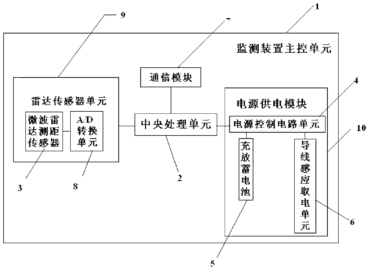
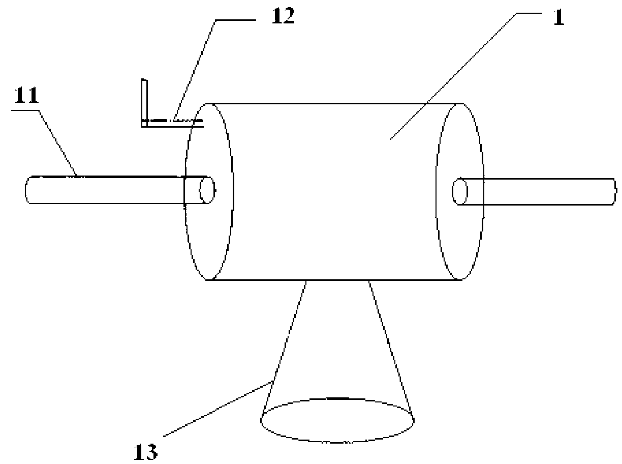
[0037] The high-voltage transmission conductor sag measuring device of the present invention has a structure such as figure 1 As shown, the measuring device housing is included, and the measuring device housing is arranged on the power transmission wire 11. The surface of the measuring device housing is respectively provided with a radar waveguide port 13 and a radio frequency antenna 12. The measuring device housing includes a monitoring device main control unit 1. The main control unit 1 of the monitoring device includes a central processing unit 2. The central processing unit 2 is respectively connected to the radar sensor unit 9 and the power supply unit 10 through wires. The central processing unit 2 also communicates with the data on the transmission tower through the communication module 7. The monitoring terminal and the communication...


PUM


Abstract

The invention discloses a high voltage transmission conductor sag measuring device. The measuring device comprises a measuring device shell body which is arranged on a transmission conductor. A radar waveguide opening and a radio frequency antenna are arranged on the surface of the measuring device shell body respectively. A monitoring device main control unit is arranged in the measuring device shell body. The monitoring device main control unit comprises a central processing unit which is connected with a radar sensor unit and a power supply unit respectively through wires. The central processing unit is further connected with a data monitoring terminal and a monitoring center respectively through a communication module. The invention further discloses a measuring method of the measuring device, wherein the radar sensor unit is used for transmitting collected sag information to the central processing unit, and then the central processing unit conducts calculation to obtain a transmission conductor sag value. The high voltage transmission conductor sag measuring device and method can monitor the changes in the sag of a high voltage transmission line in real time and transmit the monitoring data to the backstage monitoring center, thereby guaranteeing the safe operation of an electric power circuit.

Description

technical field [0001] The invention belongs to the technical field of power transmission and transformation equipment monitoring, and in particular relates to a high-voltage transmission conductor sag measurement device, and also relates to a method for measuring sag by the high-voltage transmission conductor sag measurement device. Background technique [0002] The sag of the high-voltage transmission conductor is an important indicator for the safe operation of the line. The size of the sag of the conductor should be controlled within a certain range. And cause disconnection grounding fault, even destroy the pole tower structure erecting the wire or the wind blows the cycloid to cause phase-to-phase short circuit, generate arc and spark to ignite the surrounding combustibles. [0003] In recent years, due to the sharp increase in power load, many transmission lines have increased the maximum allowable temperature of the conductor from 70°C to 80°C in order to improve the ...

Claims


Application Information

Patent Timeline
Patent Type & Authority Applications(China)
IPC IPC(8): G01B7/02
Inventor 黄新波张晓伟赵隆魏旭张亚维张烨
Owner XI'AN POLYTECHNIC UNIVERSITY
Why Eureka
Try Eureka