Automatic wire winding device of motor stator

A technology of automatic winding and motor stator, applied in electromechanical devices, electric components, manufacturing of motor generators, etc., can solve the problems of low full rate of stator slots, high labor intensity, low efficiency, etc., and achieve high full rate of finished stator slots. , The effect of low labor intensity and high work efficiency

Inactive Publication Date: 2013-10-09
李宗智
View PDF3 Cites 10 Cited by
  • Summary
  • Abstract
  • Description
  • Claims
  • Application Information

AI Technical Summary

Problems solved by technology

[0002] The motor stator is generally composed of the main body and the wires in the outer circular winding groove of the body. At present, the winding processing of the wires in the winding groove is generally carried out manually. This processing method is not only low in efficiency, but also labor-intensive. It is easy to cause damage to the hands of the operator
In addition, when winding by hand, multiple wires are generally gathered into one strand and then embedded into the winding slot, and the overall diameter of the gathered wires is larger than the inlet gap of the winding slot, which makes it easy to cause problems during the embedding process. The damage and peeling of the outer insulation layer of the wire seriously affects the winding quality, the number of winding turns is not easy to control, the product qualification rate is low, and the stability is poor
Furthermore, the above-mentioned winding method of embedded strands requires a lot of effort when winding, but in actual processing, in order to consider the delivery efficiency, the operator will not pull very tightly, so that the wire strands wound in different times The gap between the strands and the strands is very large, which leads to a relatively low slot fill rate of the stator, and also exposes a large number of wires, which not only wastes wires but also affects the working stability of the stator

Method used


Image

  • Automatic wire winding device of motor stator
  • Automatic wire winding device of motor stator
  • Automatic wire winding device of motor stator

Examples


Embodiment Construction

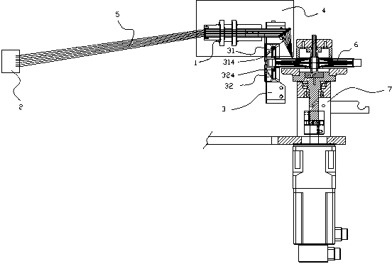
[0023] Such as figure 1 As shown, an automatic winding device for a motor stator includes a wire winding mechanism and a stator positioning mechanism.

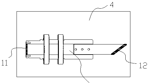
[0024] The wire winding mechanism is composed of a moving nozzle 1 , a wire compactor 2 and a wire guide 3 . The moving nozzle 1 can rotate relative to itself and is arranged on a two-axis moving device 4 that can make it move in a plane relative to a vertical plane. The interior of the whole moving wire nozzle 1 is hollow, and the two ends are respectively provided with a single-row wire inlet hole 11 and a single outlet wire hole 12 for a single row of wires 5, and its structure is as follows image 3 shown.

[0025] A spring buffer device is arranged inside the wire compactor 2 , and the entire wire compactor 2 is arranged at a certain distance relative to the moving nozzle 1 .

[0026] Such as Figure 4 As shown, the thread-laying guide 3 is divided into an upper guide 31 and a lower guide 32, and the upper and lower g...


PUM


Abstract

The invention discloses an automatic wire winding device of a motor stator. The automatic wire winding device of the motor stator comprises a wire winding mechanism and a stator positioning mechanism, wherein the wire winding mechanism is composed of a moving wire nozzle, a wire compressing device and a wire-embedding guiding device, the moving wire nozzle can revolve on the axis and is arranged on a double-axis moving device which enables the moving wire nozzle to make planer motion relative to the vertical plane, the entire moving wire nozzle is hollow, and a single-row wire inlet hole and a single-row wire outlet hole which are used for arranging wires in a single row are respectively formed in the two ends of the moving wire nozzle. The automatic wire winding device of the motor stator is designed by imitating manual wire winding operational motions, automatically enables a plurality of the wires to pass through a wire inlet interval between an upper guiding device and a lower guiding device while the wires are arranged one by one, further guides the wires into a stator winding groove, and has the advantages of being high in work efficiency, low in labor intensity, high in groove filling rate of finished stators, high in pass percentage, free of damage to the wires, and small in material consumption.

Description

technical field [0001] The invention relates to an automatic processing device, in particular to an automatic winding device for a motor stator. Background technique [0002] The motor stator is generally composed of the main body and the wires in the outer circular winding groove of the body. At present, the winding processing of the wires in the winding groove is generally carried out manually. This processing method is not only low in efficiency, but also labor-intensive. It is easy to cause damage to the hands of the operator. In addition, when winding by hand, multiple wires are generally gathered into one strand and then embedded into the winding slot, and the overall diameter of the gathered wires is larger than the inlet gap of the winding slot, which makes it easy to cause problems during the embedding process. The damage and peeling of the outer insulation layer of the wire seriously affects the winding quality, the number of winding turns is not easy to control, ...

Claims


Application Information

Patent Timeline
Patent Type & Authority Applications(China)
IPC IPC(8): H02K15/085
Inventor 李宗智
Owner 李宗智
Why Eureka
Try Eureka