Electromagnetic pulse welding device for welding metal sheets using cooling insulator

A technology of pulse welding and electromagnetic pulse, which is applied in the direction of coil devices, welding equipment, metal processing equipment, etc., and can solve problems such as premature fracture of coils

Active Publication Date: 2013-10-09
PST PRODS
View PDF7 Cites 12 Cited by
  • Summary
  • Abstract
  • Description
  • Claims
  • Application Information

AI Technical Summary

Problems solved by technology

Therefore, in this load region, the potential threat is premature fracture of the coil

Method used


Image

  • Electromagnetic pulse welding device for welding metal sheets using cooling insulator
  • Electromagnetic pulse welding device for welding metal sheets using cooling insulator
  • Electromagnetic pulse welding device for welding metal sheets using cooling insulator

Examples


Embodiment Construction

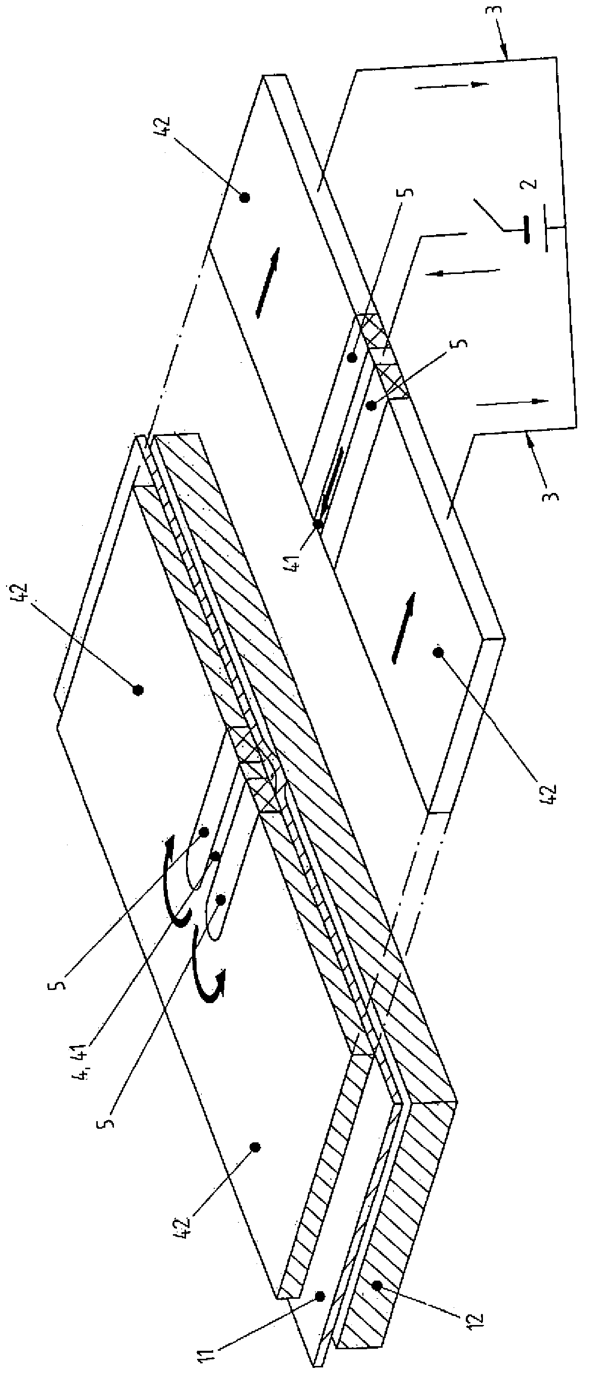
[0064] figure 1 An oblique view of a single-winding coil in the form of E is shown, cut transversely to the three legs of E. Said portion is continuous along a metal plate 11 which is arranged below and which is to be welded together with a metal part 12 located below it.

[0065] In the right-hand part of the coil 4, which is shown in section in the figure, it can be seen that the active part 41 is located in the centre. In each case it is adjacent to two opposite outer surfaces of the cooling insulator 5 , which are marked by means of cross-hatched end faces. The passive part 42 of the coil 4 is adjacent to the two other surfaces of each cooling insulator 5 .

[0066] exist figure 1 , the arrows show how the current flows from the power source 2 through the coil 4: when the switch is closed, the current flows into the active part 41 and then through the part of the coil 4 which is cut away in the figure and is therefore not visible , then enter the area shown at the top....


PUM


Abstract

The invention relates to an electromagnetic pulse-welding device for joining a metal sheet to a metal part, consisting of an electric energy source which is connected to a coil by means of a current conductor, the active part of said coil being in the direct proximity of the metal sheet, said metal sheet being at a distance from the metal part. The passive part of the coil has a larger cross-section than the active part and said active part borders on one part of the surface in a positive fit, to a cooling insulator, the material having a relatively high thermal conductivity and a relatively low magnetic and electric conductivity compared to the material of the coil.

Description

technical field [0001] The present invention relates to an electromagnetic pulse welding device for joining metal sheets to metal parts, said device comprising a power source connected by an electrical conductor to a coil, the active part of which extends in the immediate vicinity of the metal sheet , the metal plate is spaced apart from the metal part. Background technique [0002] In the prior art it is known that the term "explosive welding" signifies that, in order to join a metal plate to a distant metal part, the metal plate strikes the metal part with a strip-like portion of its surface, especially at an acute angle And a speed of at least 100m / s, that is, at least 360km / h. [0003] Another feature of the method is that the metal plate is separated from the metal part by a short distance before welding, which distance acts as an acceleration path. During this process, the air between the metal parts is so violently accelerated and compressed that it acts almost as a...

Claims


Application Information

Patent Timeline
Patent Type & Authority Applications(China)
IPC IPC(8): B23K13/01B23K20/06H05B6/36H05B6/42
CPCB23K20/06H05B6/36B23K13/01H05B6/42
Inventor 巴勃罗·珀斯夸尔
Owner PST PRODS
Why Eureka
Try Eureka