Method and device for large field of view imaging and detection and compensation of motion artifacts

A motion and motion map technology, which is applied in the directions of instruments, applications, and image enhancement for radiological diagnosis, and can solve problems such as inaccurate motion compensation effects.

Active Publication Date: 2015-09-23
KONINKLIJKE PHILIPS ELECTRONICS NV
View PDF8 Cites 0 Cited by
  • Summary
  • Abstract
  • Description
  • Claims
  • Application Information

AI Technical Summary

Problems solved by technology

While such methods can improve image quality for certain types of motion, the motion compensation effects achieved by these methods are often imprecise, and they can also introduce artifacts to areas of the image that are not affected by any motion

Method used


Image

  • Method and device for large field of view imaging and detection and compensation of motion artifacts
  • Method and device for large field of view imaging and detection and compensation of motion artifacts
  • Method and device for large field of view imaging and detection and compensation of motion artifacts

Examples


Embodiment Construction

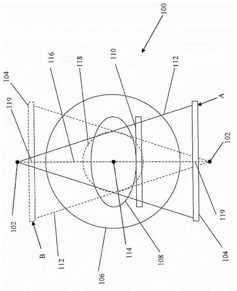
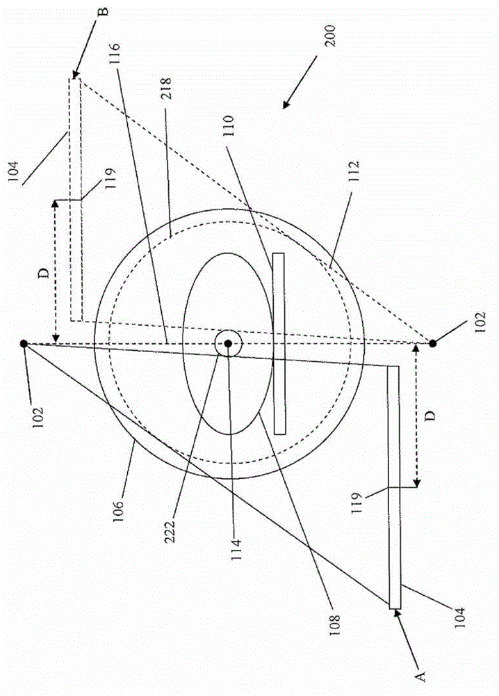
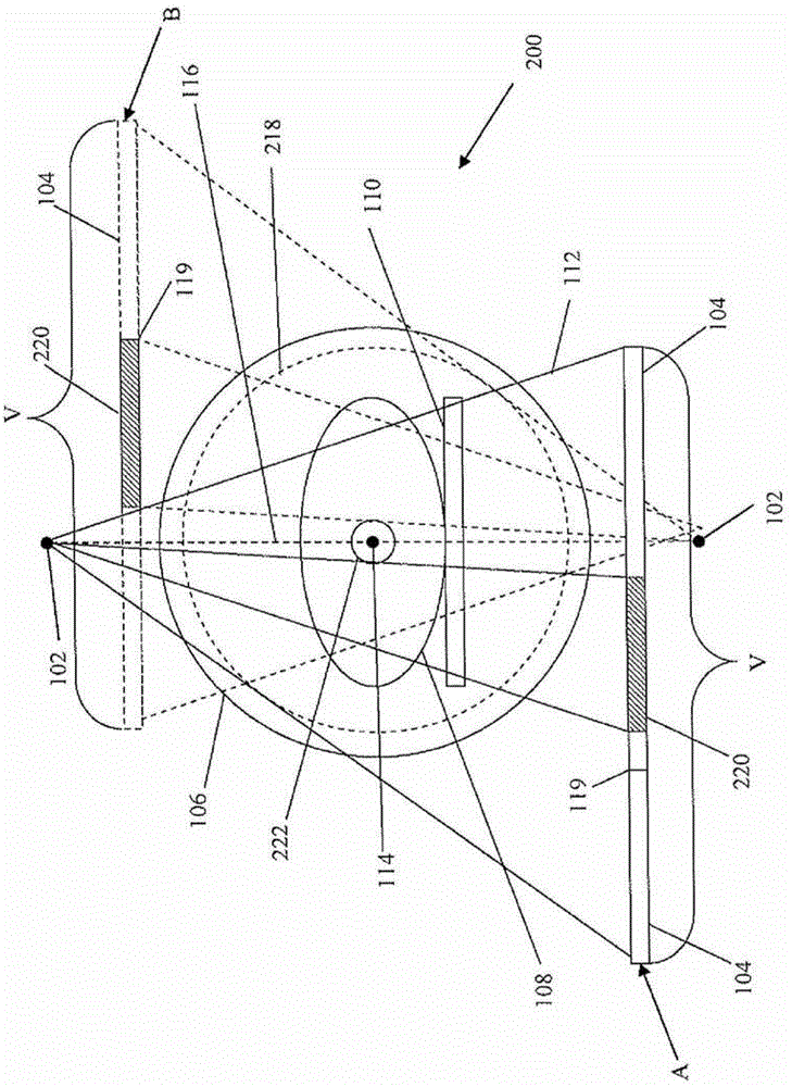
[0023] One aspect of the present invention relates generally to methods and apparatus for CT image acquisition, and more particularly to methods for providing a large field of view with improved image quality by utilizing at least two scanning procedures performed by a CT imaging apparatus (“ FOV") method and apparatus. At least one scan employs the radiation source and detector of the CT imaging device in a centered geometry, and at least one scan employs the detector and / or source in an offset geometry. The image data obtained from the at least two scanning procedures are then combined to generate a reconstructed image.

[0024] figure 1 An exemplary centering geometry 100 of a CT imaging apparatus is described. The exemplary centering geometry 100 has an X-ray source 102, such as an X-ray tube, and an X-ray sensitive detector 104, such as a flat panel area detector array extending in transverse and axial directions. Such as figure 1 As shown, the center of rotation 114 ...


PUM


Abstract

A method and apparatus are provided to improve large field of view CT image acquisition by using at least two scanning procedures: (i) one with the radiation source and detector centered and (ii) one in an offset configuration. The imaging data obtained from both of the scanning procedures is used in the reconstruction of the image. In addition, a method and apparatus are provided for detecting motion in a reconstructed image by generating a motion map that is indicative of the regions of the reconstructed image that are affected by motion artifacts. Optionally, the motion map may be used for motion estimation and / or motion compensation to prevent or diminish motion artifacts in the resulting reconstructed image. An optional method for generating a refined motion map is also provided.

Description

[0001] This application is a divisional application filed on December 23, 2009 with application number 200980156960.4 and titled "Method and Device for Detection and Compensation of Large Field of View Imaging and Motion Artifacts". technical field [0002] This application relates generally to the field of imaging. In one embodiment, methods and apparatus are provided for imaging large objects. In another embodiment, it provides detection and compensation of motion artifacts when reconstructing tomographic images. The subject matter of the present application is applicable at least to computed tomography (CT) imaging, and more particularly to flat panel detector cone beam computed tomography (CBCT) imaging, and will be described with particular reference thereto. However, the application also has more general application in other imaging methods and in other fields. technical background [0003] A conventional CT imaging device includes an X-ray source and an X-ray sensit...

Claims


Application Information

Patent Timeline
Patent Type & Authority Patents(China)
IPC IPC(8): A61B6/03
CPCA61B6/4085A61B6/587A61B6/4452G06T11/005A61B6/5217A61B6/4233A61B6/032G06T2211/412A61B6/542A61B6/488G16H50/30G06T5/20G06T7/20G06T2207/10116G06T2207/20032G06T2211/40
Inventor C·施雷特M·贝尔特拉姆C·诺伊基兴
Owner KONINKLIJKE PHILIPS ELECTRONICS NV
Why Eureka
Try Eureka