Elastic ribbon machine

A technology of elastic machine and elastic belt, which is applied in the direction of cloth feeding mechanism, sewing machine components, manufacturing tools, etc., achieves the effect of improving loop forming speed, simple structure, and convenient sewing and fixing.

Active Publication Date: 2013-10-16
NINGBO SUPREME ELECTRONIC MASCH INC
View PDF11 Cites 40 Cited by
  • Summary
  • Abstract
  • Description
  • Claims
  • Application Information

AI Technical Summary

Benefits of technology

This patented technology allows for faster and more efficient welding processes when transferring elongated materials such as rubber bands onto fabric or other items during manufacturing operations. By adjusting the movement angles of one part (the drive wheels) while another part moves around it, this system enables longer lengths of elastomeric material being transferred without stopping until needed again. It also includes a mechanism where the elastomers enter into specific sections before they exit from their respective roller devices. These sections then work together to create rings made up entirely of elastic elements attached to a supporting framework like clothings.

Problems solved by technology

This patented technical problem addressed by these inventors relates how to improve the efficiency and accuracy of producing elastings with automated machines that have been developed earlier than before.

Method used


Image

  • Elastic ribbon machine
  • Elastic ribbon machine
  • Elastic ribbon machine

Examples


Embodiment Construction

[0022] Embodiments of the present invention will be described in further detail below in conjunction with the accompanying drawings.

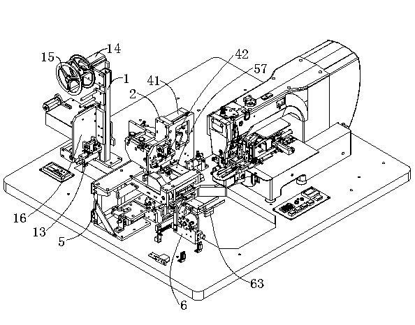
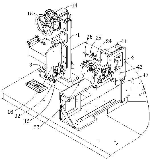
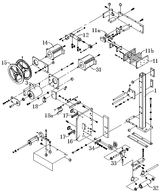
[0023] Figure 1 to Figure 7 Shown is the structural representation of the present invention.

[0024] Wherein the reference numerals are: first frame 1, heating plate 11, heating guide rail 11a, electric heating rod 11b, heating cylinder 12, material storage sensor 13, third motor 14, material handling roller 15, backing plate 16, Adjust the limit block 17, the joint sensor 18, the induction flap 18a, the second frame 2, the first installation substrate 21, the second installation substrate 22, the third installation substrate 23, the feeding pallet 24, the driven wheel shaft 25, Adjusting block 26, the first feeding driving wheel 3, the first motor 31, the first feeding driven wheel 32, the first driven wheel mounting bracket 33, the first spring 34, the second feeding driving wheel 4, the rotating drive shaft 4a, the second Motor 41, first...


PUM


Abstract

The invention discloses an elastic ribbon machine. By control over the rotation angle of a first motor, the lengths of conveyed elastic ribbons can be set, elastic ribbons conveyed in through a first feeding driving wheel are stored between the first feeding driving wheel and a second feeding driving wheel, and therefore the second feeding driving wheel is matched with a roll material coiling device to continuously output the elastic ribbons. In a feeding process, the elastic ribbon machine can conduct joint examination and ironing on the elastic ribbons, and the elastic ribbons at the discharging port of the second feeding driving wheel can be cut off automatically through a cutting device. The roll material coiling device clamps materials through a third fixture and rotates to enable the two ends of each elastic ribbon to be respectively sent to a first fixture and a second fixture; the first fixture and the second fixture clamp the two ends of each elastic ribbon and enable each elastic ribbon to form an elastic ring through rotation motion, and the two spliced ends of each elastic ring are fixed on a material supporting frame to facilitate following sewing fixation. The roll material coiling device has the advantages of being simple in structure and achieving automatic control, and greatly improves the coiling speed of the elastic ribbons.

Description


Claims


Application Information

Patent Timeline
Owner NINGBO SUPREME ELECTRONIC MASCH INC
Why Eureka
Try Eureka