Shell-and-tube heat exchanger with rotary jet-flow baffle plates

A technology of shell-and-tube heat exchangers and baffles, which is applied in the direction of heat exchanger types, heat exchanger shells, indirect heat exchangers, etc., which can solve the difficulties in installing spiral baffles, difficulty in ensuring product accuracy, and unfavorable industrial conditions. Standardization and other issues to achieve the effect of simple structure, reduced flow resistance, and reduced flow dead zone

Inactive Publication Date: 2013-10-16
TAIYUAN UNIV OF TECH
View PDF5 Cites 13 Cited by
  • Summary
  • Abstract
  • Description
  • Claims
  • Application Information

AI Technical Summary

Problems solved by technology

Although this type of spiral baffle makes the flow form of the shell side fluid more reasonable, increases the effective flow area, and reduces the flow resistance, but compared with the bow-shaped baffle, the spiral baffle is difficult to install, the processing cost is high, and the product accuracy is difficult. Guaranteed, detrimental to industry standardization

Method used


Image

  • Shell-and-tube heat exchanger with rotary jet-flow baffle plates
  • Shell-and-tube heat exchanger with rotary jet-flow baffle plates
  • Shell-and-tube heat exchanger with rotary jet-flow baffle plates

Examples


Embodiment Construction

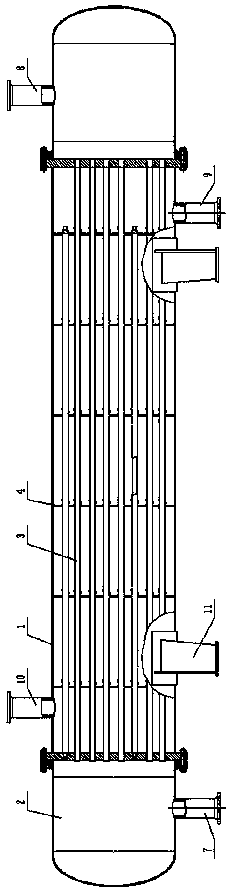
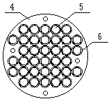
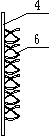
[0016] Such as figure 1 , figure 2 , image 3 As shown, a shell-and-tube heat exchanger with a rotating jet baffle includes: a shell 1 and tube boxes 2 arranged at both ends of the shell 1, wherein a tube side is arranged on the tube box 2 at one end of the shell 1 Fluid inlet, the tube box 2 at the other end is provided with a tube-side fluid outlet, and the shell 1 is provided with a shell-side fluid inlet and a shell-side fluid outlet. The heat exchange tubes 3 are provided with a plurality of baffles 4 arranged in parallel, and each baffle 4 is provided with a plurality of through holes 5, and each heat exchange tube 3 passes through the through holes 5 vertically and runs through each baffle 4. A plurality of swirl fins 6 are arranged in the through hole 5 of each baffle 4 .

[0017] The shape and direction of rotation of the swirl vanes 6 are the same.

[0018] In the orthographic projection of the baffle plate 4 , the swirl fin 6 is in the shape of a ring, the oute...


PUM


Abstract

The invention relates to a shell-and-tube heat exchanger with rotary jet-flow baffle plates, in particular to a shell-and-tube heat exchanger used for heat exchanging between two fluid media in the fields such as nuclear energy, power, oil refining, chemical engineering and petrochemical engineering. The shell-and-tube heat exchanger with the rotary jet-flow baffle plates is simple and reasonable in structure, capable of effectively reducing flow resistance, enlarging the flow area, improving turbulence effect, and reducing shell side dead zones, and high in heat exchanging efficiency. According to the technical scheme, the shell-and-tube heat exchanger with the rotary jet-flow baffle plates comprises a shell body and tube boxes arranged on the two ends of the shell body, a tube side fluid inlet is formed in the tube box at one end of the shell body, a tube side fluid outlet is formed in the tube box at the other end, a shell side fluid inlet and a shell side fluid outlet are formed in the shell body, heat exchanging tubes and the baffle plates are arranged inside the shell body, a plurality of through holes are formed in each baffle plate, the heat exchanging tubes are perpendicular to the baffle plates and penetrate through the baffle plates, and a plurality of jet-flow pieces are arranged in each through hole of each baffle plate. The shell-and-tube heat exchanger with the rotary jet-flow baffle plates is mainly used for heat exchanging between fluid media.

Description

technical field [0001] The invention relates to a shell-and-tube heat exchanger with a rotating jet baffle, in particular to a shell-and-tube heat exchanger used for heat exchange between two fluid media in the fields of nuclear energy, power, oil refining, chemical industry, petrochemical industry, etc. heater. Background technique [0002] Shell and tube heat exchangers are widely used in petrochemical, electric power, environmental protection and other industrial fields. Shell and tube heat exchangers usually include tube boxes, tube sheets, shells, multiple baffles, multiple heat exchange tubes, tie rods and spacer tubes, etc. Among them, in addition to supporting the heat exchange tubes in the shell of the shell-and-tube heat exchanger, the baffle mainly functions to make the shell-side fluid flow according to a specific path, increase the flow velocity of the shell-side fluid, increase the degree of turbulence, and improve heat transfer characteristics. role. [000...

Claims


Application Information

Patent Timeline
Patent Type & Authority Applications(China)
IPC IPC(8): F28D7/16F28F9/24
CPCY02P20/10
Inventor 孙海阳刘晓东
Owner TAIYUAN UNIV OF TECH
Why Eureka
Try Eureka