
Carbon nanotube based x-ray tube and mobile ct scanner

A technology of carbon nanotubes and X-ray tubes, applied in X-ray tubes, computerized tomography scanners, instruments for radiological diagnosis, etc., which can solve the problems of high cost, prolonged unit sampling time, complex structure and control of X-ray tubes, etc. problem, to achieve the effect of fast response and long service life

Active Publication Date: 2016-04-27
THE MILITARY GENERAL HOSPITAL OF BEIJING PLA
View PDF8 Cites 0 Cited by
  • Summary
  • Abstract
  • Description
  • Claims
  • Application Information

AI Technical Summary

Problems solved by technology

If the number of projection angles for one rotation is reduced, the unit sampling time must be extended, and the projections of adjacent voxels on the concentric circle of the imaging object will overlap, resulting in motion artifacts
Although today's high-end CT scanners use flying focus technology to overcome motion artifacts, this leads to a very complex and costly X-ray tube structure and control

Method used


Image

  • Carbon nanotube based x-ray tube and mobile ct scanner
  • Carbon nanotube based x-ray tube and mobile ct scanner
  • Carbon nanotube based x-ray tube and mobile ct scanner

Examples


Embodiment Construction

[0025] In order to make the purpose, technical solutions and advantages of the embodiments of the present invention clearer, the technical solutions in the embodiments of the present invention will be clearly and completely described below in conjunction with the drawings in the embodiments of the present invention. Obviously, the described embodiments It is a part of embodiments of the present invention, but not all embodiments. Elements and features described in one drawing or one embodiment of the present invention may be combined with elements and features shown in one or more other drawings or embodiments. It should be noted that representation and description of components and processes that are not related to the present invention and known to those of ordinary skill in the art are omitted from the drawings and descriptions for the purpose of clarity. Based on the embodiments of the present invention, all other embodiments obtained by persons of ordinary skill in the ar...


PUM


Abstract

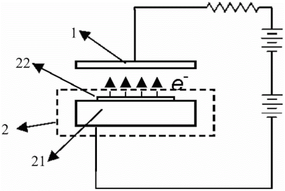
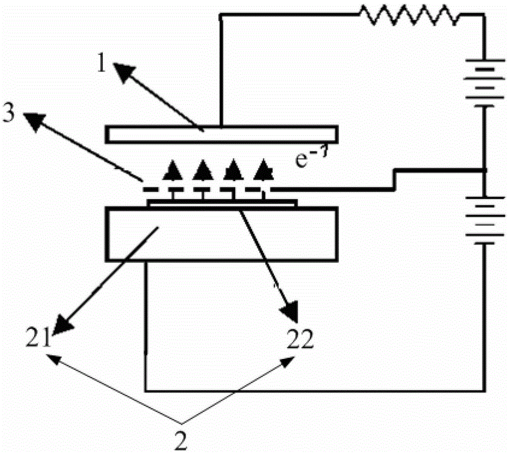
A carbon nanotube-based X-ray tube and a movable CT scanner. The carbon nanotube-based X-ray tube comprises an anode (1) and a carbon nanotube cathode (2). Electrons generated by field emission of the carbon nanotube cathode (2) under the effect of an external electric field bombard the anode (1) to generate X-rays. High-frequency pulse transmission can be implemented very easily by using a carbon nanotube to develop an X-ray tube, the response speed is fast, and the service life is long, and accordingly, an inherent defect of the existing wolfram (W) thermal filament X-ray source is overcome, and practical application demands such as a medical detection can be better met.

Description

technical field [0001] The invention relates to a cold cathode X-ray tube, in particular to an X-ray tube based on carbon nanotubes and a mobile CT scanner. Background technique [0002] The current medical X-ray sources mainly use tungsten (W) hot filament X-ray tubes. The basic principle is: electrify the filament to heat, when the temperature of the filament reaches thousands of degrees Celsius, thermionic electrons are emitted, and the thermal electrons converge under the action of the electric field force and accelerate to hit the anode, thereby generating X-rays. The mode in which thermal emission generates electrons leads to slow start-up and short lifetime of such X-ray sources. The cumulative exposure time of the X-ray tube with rotating anode is generally only tens of hours, and the cumulative exposure time of the X-ray tube with fixed anode is about 2000 hours. [0003] When continuous pulse scanning is required, the traditional X-ray source cannot turn off the ...

Claims


Application Information

Patent Timeline
Patent Type & Authority Patents(China)
IPC IPC(8): A61B6/03
CPCA61B6/032A61B6/405H01J35/065H01J2201/30469
Inventor 徐如祥高枫
Owner THE MILITARY GENERAL HOSPITAL OF BEIJING PLA
Learn More