
Scene modeling method under single camera and system

A single-camera, scene modeling technology, applied in the field of scene modeling, can solve problems such as inability to adapt to scene changes, inconspicuous dot matrix imaging, and unoptimized image coordinates

Inactive Publication Date: 2012-04-18
成都神州数码索贝科技有限公司
View PDF0 Cites 1 Cited by
  • Summary
  • Abstract
  • Description
  • Claims
  • Application Information

AI Technical Summary

Problems solved by technology

[0004] (1) It is necessary for a person to enter the scene with a calibration board, which may be inconvenient or impossible in some application environments
[0005] (2) It is necessary to manually select the imaging points of all the points on the calibration board in each orientation to determine the image coordinates of these points, which is cumbersome and error-prone
[0006] (3) The selected image coordinates cannot be optimal
Especially when the calibration board is small, the dot matrix imaging on the board is less obvious, which will seriously affect the positioning of the image coordinates
[0007] (4) Cannot adapt to scene changes
Once the model is successfully established, it is required that the camera cannot be changed. When the camera changes and the shooting scene changes (such as: the position of the camera shifts, or the focal length changes, etc.), the model must be re-established, otherwise it will seriously affect the calculation. result
[0008] (5) Multiple videos of different scenes cannot be processed at the same time
[0009] From the above five points, it can be seen that the current scene modeling technology is not flexible, and even cannot be implemented in some occasions, which brings great difficulties to video applications such as surveillance

Method used


Image

  • Scene modeling method under single camera and system
  • Scene modeling method under single camera and system
  • Scene modeling method under single camera and system

Examples


Embodiment 1

[0065] Embodiment 1, a scene automatic modeling system under a single camera, such as figure 1 shown, including:

[0066] The moving object detection subsystem is used to detect moving objects from the video frame images captured in the current scene;

[0067] A moving object tracking subsystem, configured to track the detected moving object, and obtain the moving track of the moving object;

[0068] Determining the calibration target subsystem is used to filter out the calibration target from the motion trajectories of all moving targets. If the screening is successful, the scene modeling subsystem is started; the filtered calibration target refers to a moving target that meets the following conditions: The eigenvalue of the moving target matches the preset eigenvalue, and the moving track of the moving target includes at least three position points, these position points are not collinear, have no overlap, and the distance between each pair is greater than a preset The dis...

Embodiment 2

[0136] Embodiment 2, a scene automatic modeling method under a single camera, comprising:

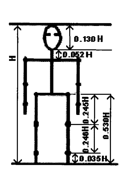
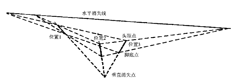
[0137] First, detect and track the moving objects entering the scene, and record their trajectories in the scene; analyze these trajectories, and select the best target that meets the conditions as the calibration object. If the selection of the calibration object is unsuccessful, then Continue to process the next frame, otherwise enter the modeling stage; when modeling, it is necessary to determine the most evenly distributed positions in the trajectory of the calibration object, extract the image coordinates of the head and foot points of the calibration object at these positions, and combine projection and The knowledge of geometry can establish scene modeling.

[0138] The method is as Figure 5 As shown, it specifically includes the following steps:

[0139] A. According to the video frame image captured in the current scene, the moving target is detected;

[0140] B. Track each...


PUM


Abstract

The invention relates to a scene modeling method under a single camera and a system. The method comprises the following steps of: detecting motion targets according to a video frame image; tracking every detected motion target to obtain motion trails of the motion targets; screening out calibration object targets from the motion trails of all the motion targets; selecting at least three positionsfrom the screened motion trails of the motion targets as calibration point positions; extracting image coordinates of highest points and lowest points of the imaging of the calibration object targetsat the calibration point positions; calculating the positions of vertical vanishing points and horizontal vanishing lines under a current scene through the coordinates and the mounting height of the camera; and building a height model. The invention does not need artificial auxiliary calibration and can automatically carry out modelling, be self-adaptive to the change of the scene and simultaneously process multiple videos of different scenes.

Description

technical field [0001] The invention relates to the field of scene modeling, in particular to a method and system for scene modeling under a single camera. Background technique [0002] In order to obtain 3D spatial information from 2D images, scene modeling is an essential step, and it is widely used in 3D reconstruction, navigation, visual monitoring and other fields. Reconstructing the true size of an object from an unmarked image sequence is a very meaningful technique with broad application prospects. For example, in the automatic navigation task of the robot, the robot obtains the two-dimensional image of the environment through observation, and then obtains the three-dimensional information of the environment through calculation to determine the walking direction, distance, height of the target in the field of view, etc.; Through scene modeling, information such as the size and speed of moving objects in the scene can be calculated, which is convenient for timely mon...

Claims


Application Information

Patent Timeline
Patent Type & Authority Patents(China)
IPC IPC(8): G06T17/00G06T7/20G06T17/05
Inventor 蒋敏谭颖潘巧海谭骁彧
Owner 成都神州数码索贝科技有限公司
Learn More