Cutter shaft structure of transverse cutting machine

A shaft structure and machine tool technology, applied in metal processing and other directions, can solve the problems of inability to meet the production needs of cross-cutting machines, fast cutter wear, and short life.

Inactive Publication Date: 2013-10-23
湖南益晟机械科技有限公司
View PDF6 Cites 7 Cited by
  • Summary
  • Abstract
  • Description
  • Claims
  • Application Information

AI Technical Summary

Problems solved by technology

For wide cardboard cutting W≥2200, such as image 3 , 4 , the knife shaft structure of the widely used cross-cutting machine drives the input gear shaft 1' through the servo motor, the input gear shaft 1' drives the lower knife gear 2', the gap adjustment gear 3' and the upper knife gear 4', the lower knife gear 2 ' is connected with the lower cutter shaft 6' by a key, and the gap adjustment gear 3' and the upper cutter gear 4' are also connected with the upper cutter shaft 5'...

Method used


Image

  • Cutter shaft structure of transverse cutting machine
  • Cutter shaft structure of transverse cutting machine
  • Cutter shaft structure of transverse cutting machine

Examples


Embodiment Construction

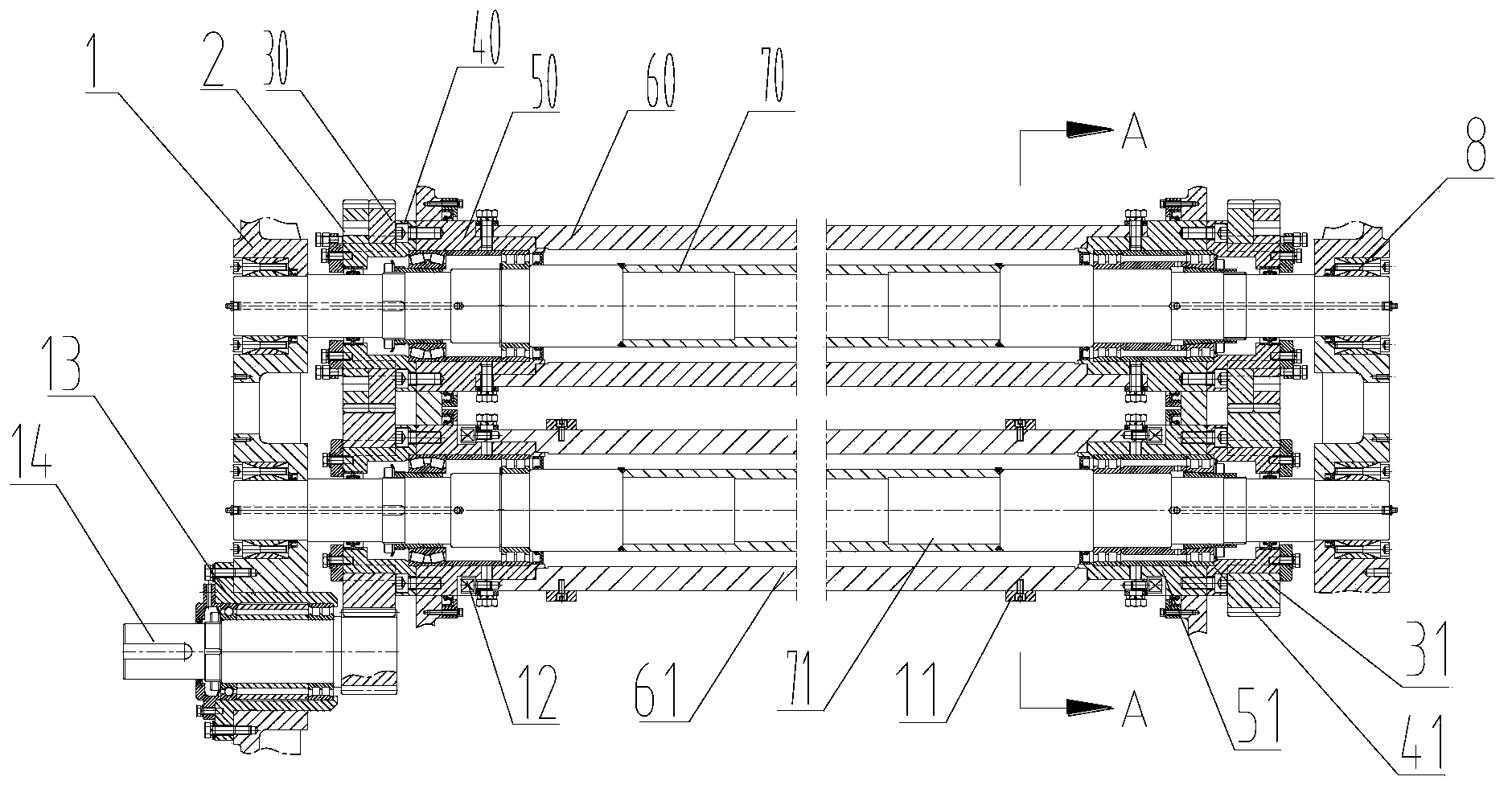
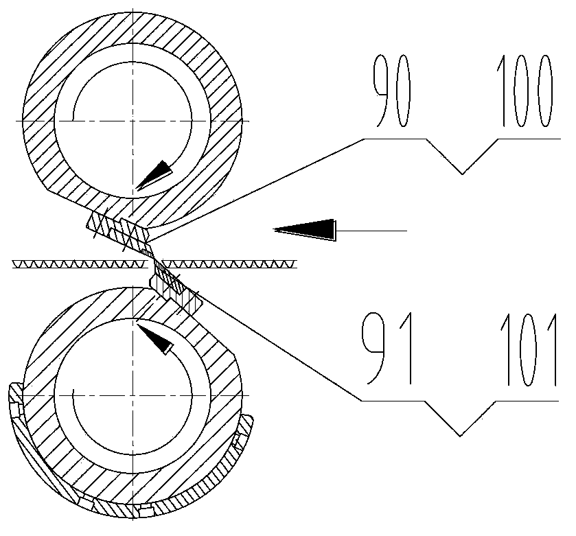
[0015] This cutter shaft transmission structure of the present invention, as figure 1 , 2 As shown, the upper knife mandrel 70 and the lower knife mandrel 71 are fixedly installed on the box body 1 through the expansion sleeve 8 respectively, and the upper knife roller bearings are respectively installed on the two ends of the upper knife mandrel 70 and the lower knife mandrel 71 Seat 50 and lower cutter roller bearing seat 51, upper cutter roller 60, lower cutter roller 61 are respectively installed on the roller bearing seats at the two ends of upper cutter mandrel 70 and lower cutter mandrel 71, on the upper cutter roller 60. The upper knife seat 90 and the lower knife seat 91 are relatively installed on the installation plane of the lower knife roller 61, and the upper knife 100 and the lower knife 101 are respectively installed on the above knife seats; the upper knife roller 60 and the lower knife roller 61 is driven by the driving structure and can rotate around the a...


PUM


Abstract

A cutter shaft structure of a transverse cutting machine is characterized in that the ends of core shafts (70 and 71) are fixedly mounted on a box body (1) through expansion sleeves (8); self-aligning roller bearings are mounted on the core shafts (70 and 71); roller bearing supports (50 and 51) are fixedly mounted on the self-aligning roller bearings and fixedly assembled with rollers (60 and 61); roller rotation driving structures are mounted on the roller bearing supports (50 and 51) and at the ends of the rollers (60 and 61); cutter holders and cutters (100 and 101) are mounted on the outer sides of the rollers (60 and 61); the core shafts (70 and 71) are fixed; the roller rotation driving structures drive the rollers (60 and 61) to rotate around the core shafts. According to the structure, the core shafts are fixed while the rollers are rotated, which reduces inertia of rotation and the weight of cutter shafts so as to achieve an energy saving effect and reduce the bearing interval; the cutter shaft structure has good cutting stability and remarkable energy saving effect when used for cross cutting of wide paper boards (W is greater than or equal to 2,200).

Description

technical field [0001] The invention relates to the technical field of packaging machinery structures, in particular to the design of a cutter shaft transmission structure when cutting wide cardboard horizontally. Background technique [0002] The cross-cutting machine is a kind of equipment used in the corrugated cardboard production line to cut the continuous corrugated cardboard horizontally into the cardboard with the required length and specification. Composition, the transmission part of the cutter shaft is its core part. The cutter shaft requires high running precision, good support rigidity, small deflection, and less cutter shaft jump. If the gap is too large, the paper will not be cut, or the blade will interfere with the knife. For wide cardboard cutting W≥2200, such as image 3 , 4 , the knife shaft structure of the widely used cross-cutting machine drives the input gear shaft 1' through the servo motor, the input gear shaft 1' drives the lower knife gear 2', th...

Claims


Application Information

Patent Timeline
IPC IPC(8): B26D7/26
Inventor 李中正欧阳钟禄段远步
Owner 湖南益晟机械科技有限公司
Why Eureka
Try Eureka