Vehicle drive device

A driving device, wheel drive technology, applied in the direction of electrical devices, power devices, transmission devices, etc.

Active Publication Date: 2013-10-23
HONDA MOTOR CO LTD
View PDF6 Cites 5 Cited by
  • Summary
  • Abstract
  • Description
  • Claims
  • Application Information

AI Technical Summary

Problems solved by technology

[0005] In recent years, the demand for energy saving, improvement in fuel efficiency, and improvement in comfort have become increasing

Method used


Image

  • Vehicle drive device
  • Vehicle drive device
  • Vehicle drive device

Examples


Embodiment Construction

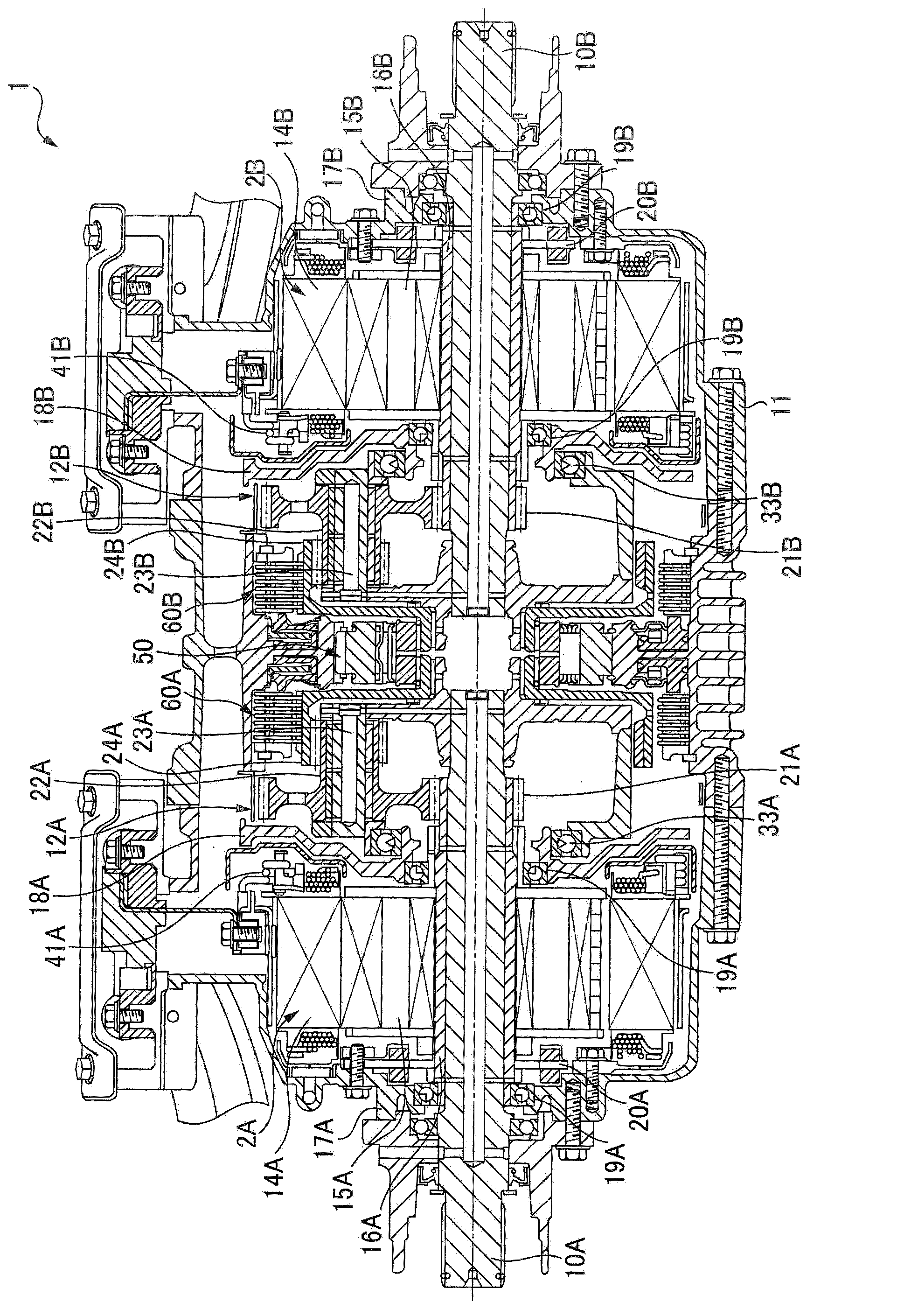
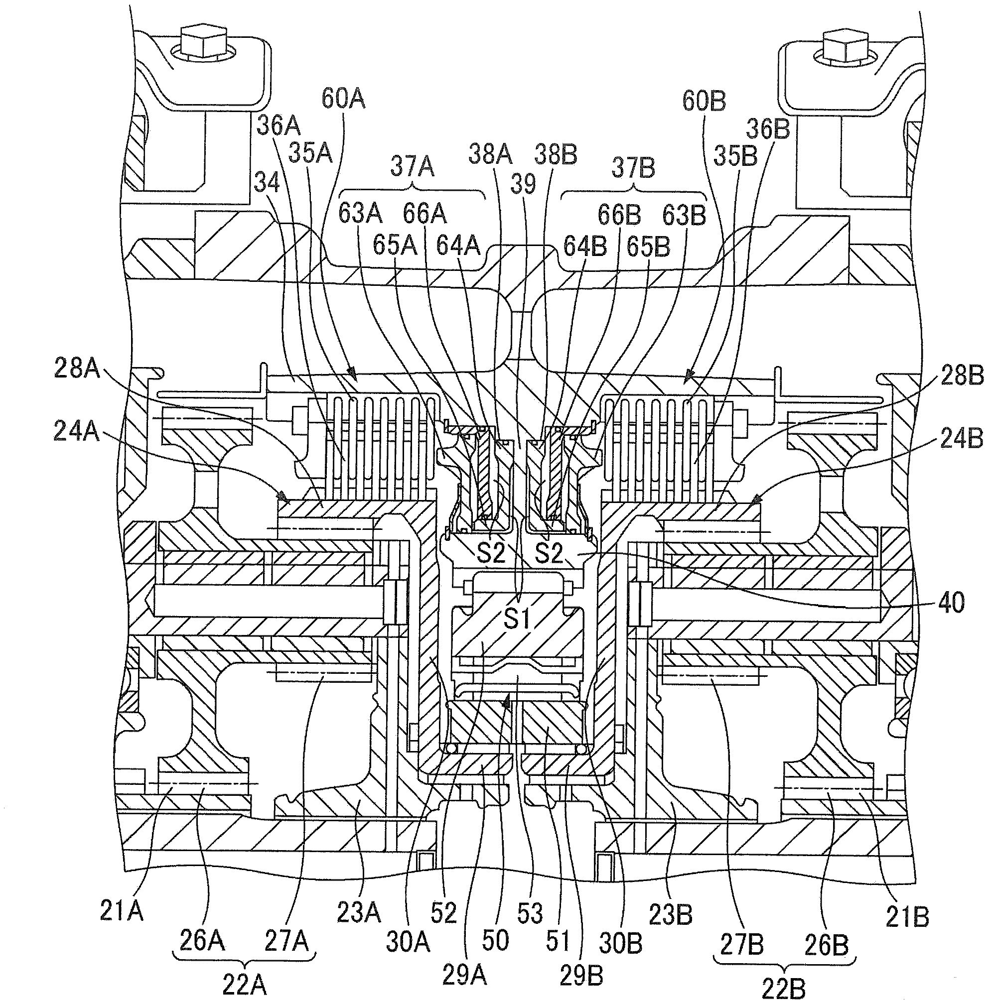
[0083] First, based on Figure 1 ~ Figure 3 , an embodiment of the vehicle drive device according to the present invention will be described.

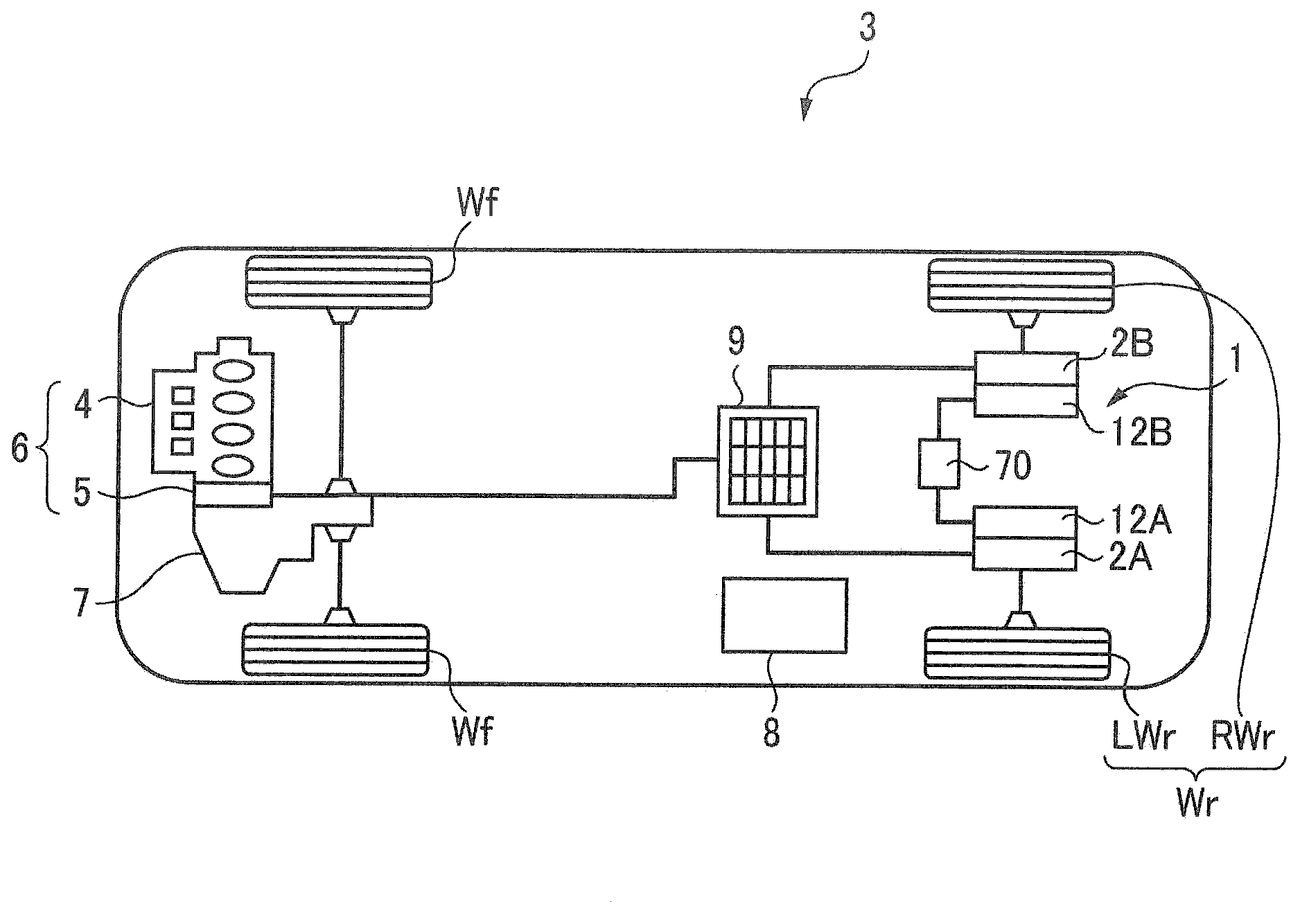
[0084] The driving device for a vehicle according to the present invention uses an electric motor as the driving source for driving the axle, and is used, for example, in figure 1 A vehicle with a drive system as shown. In the following description, a case where the vehicle drive device is used as a rear wheel drive will be described as an example, but the vehicle drive device may also be used for front wheel drive.

[0085] figure 1 The vehicle 3 shown is a hybrid vehicle having a driving device 6 (hereinafter referred to as a front-wheel drive device) in which an internal combustion engine 4 and an electric motor 5 are connected in series at the front of the vehicle. The device 7 transmits power to the front wheels Wf, and on the other hand, the drive device 1 (hereinafter referred to as a rear wheel drive device) provided at the ...


PUM


Abstract

The invention provides a vehicle drive device excellent in control performance. The vehicle drive device is configured to perform control such that a limit torque, i.e., a ring-freeing limit torque, of first and second electric motors (2A, 2B) after switching from a ring-locking state to a ring-freeing state is set to a value larger in absolute value than, or roughly equal in absolute value to, an upper limit torque or a ring-locking limit torque of the first and second electric motors (2A, 2B) under the ring-locking state at the time of switching, and the torque generated by the first and second electric motors (2A, 2B) is less than the ring-freeing limit torque.

Description

technical field [0001] The present invention relates to a vehicle drive system provided with a left wheel drive device for driving a left wheel and a right wheel drive device for driving a right wheel. Background technique [0002] Patent Document 1 discloses a driving device for a vehicle including a left wheel driving device and a right wheel driving device. The left wheel driving device has a first electric motor for driving the left wheel of the vehicle, A first planetary gear type transmission on the power transmission path of the left wheel, the right wheel drive device has a second motor that drives the right wheel of the vehicle, and a second motor that is arranged on the power transmission path between the second motor and the right wheel. Planetary gear transmission. In the first and second planetary gear transmissions, the first and second electric motors are respectively connected to the sun gear, the left wheel and the right wheel are respectively connected to ...

Claims


Application Information

Patent Timeline
IPC IPC(8): B60K17/14F16H48/32B60L50/16
CPCB60L15/00B60K17/043B60K2001/001Y02T10/648B60K1/02B60L15/2045B60K7/0007B60L3/0061B60L15/2009B60L15/2036B60L15/2054B60L2220/46B60L2240/12B60L2240/36B60L2240/421B60L2240/423B60L2240/425B60L2240/485B60L2240/486B60L2240/507B60L2240/545B60L2240/547B60L2240/549B60L2260/28B60L2220/50Y02T10/72B60L50/61B60L50/16B60L58/12B60L50/66B60K17/046B60K2007/0046B60K2007/0092B60Y2400/427Y02T10/62Y02T10/64Y02T10/70Y02T10/7072
Inventor 野口真利菊地政幸
Owner HONDA MOTOR CO LTD
Why Eureka
Try Eureka