A variable camber trailing edge and leading edge for an aircraft wing

A wing leading edge and wing technology, applied in wing adjustment, aircraft transmission, aircraft power transmission, etc., can solve the problem of poor invisibility, difficulty in adapting to a wide range of flight conditions, difficulty in wing skin installation, and reduced aircraft safety To achieve the effect of improving combat maneuverability and safety, improving cruising capability, and reducing radar echoes

Active Publication Date: 2016-05-18
HARBIN INST OF TECH SHENZHEN GRADUATE SCHOOL
View PDF7 Cites 1 Cited by
  • Summary
  • Abstract
  • Description
  • Claims
  • Application Information

AI Technical Summary

Problems solved by technology

However, memory titanium alloy is usually used for flexible deformation, which has disadvantages such as high cost, heavy weight, and low expandability. The key is to achieve flexible deformation without too much rigidity, which is different from the high rigidity performance required by aircraft to resist harsh environments. Inconsistency will greatly reduce the safety of the aircraft; while the mechanical multi-chip multi-stage series adjustment scheme has shortcomings such as heavy weight and difficult wing skin installation. In addition, the wing contains a large number of mechanical sheet structures that reduce the concealment of the aircraft. especially fighter jets
Therefore, these technical solutions have limited functions, low efficiency, low security, poor invisibility and are difficult to adapt to changes in a wide range of flight conditions

Method used


Image

  • A variable camber trailing edge and leading edge for an aircraft wing
  • A variable camber trailing edge and leading edge for an aircraft wing
  • A variable camber trailing edge and leading edge for an aircraft wing

Examples


Embodiment 1

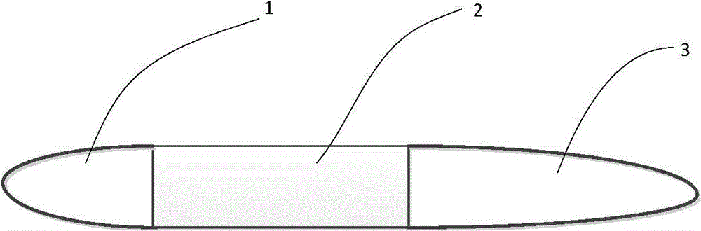
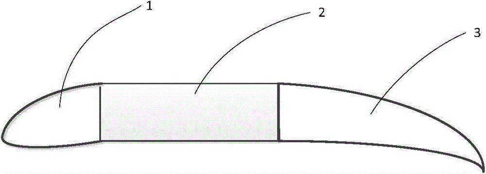
[0035] Such as Figure 1-2 As shown, the present embodiment provides a kind of aircraft wing, and this aircraft wing comprises wing leading edge 1, wing middle part 2, wing trailing edge 3, wing skin 4; Wherein, wing leading edge 1 camber Variable, 2 cambers in the middle of the wing are not variable, and 3 cambers at the trailing edge of the wing are variable.

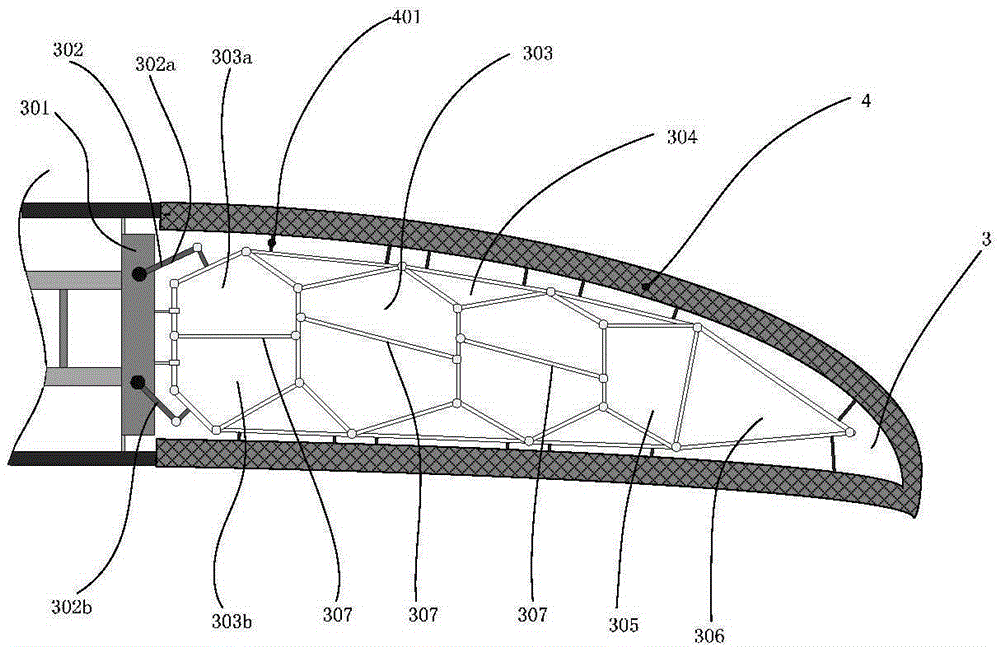
[0036] Such as image 3 As shown, the wing middle part 2 with constant camber includes a main beam; the trailing edge 3 with a variable camber includes a rear beam 301, multiple groups (for example, four groups) of trailing edge rod group structures and trailing edge drive mechanisms arranged in parallel; the rear beam 301 is connected to the rear end of the main beam; the rear edge drive mechanism includes a rocker 302 driven by the driving device, one end of the rocker 302 is rotatably connected to the rear beam 301, and the other end of the rocker 302 is rotatably connected to the rear edge rod group structure; T...


PUM


Abstract

The invention provides a trailing edge with adjustable degrees of curvature for an aircraft wing. The aircraft wing comprises a middle wing part with the fixed degree of curvature. The middle wing part comprises a main beam. The trailing edge with the adjustable degrees of curvature comprises a rear beam, a plurality of trailing edge pole group structures and a trailing edge driving mechanism, wherein the trailing edge pole group structures are arranged in parallel. The rear beam is connected with the rear end of the main beam. The trailing edge driving mechanism comprises rockers driven by a driving device. One ends of the rockers are connected with the rear beam in a rotatable mode, and the other ends of the rockers are connected with the trailing edge pole group structures in a rotatable mode. The trailing edge pole group structures are plane pole group structures based on 5R closed-loop units and respectively have one degree of freedom. Each trailing edge pole group structure comprises a plurality of pairs of 5R closed-loop units, a plurality of networking triangular units, a tail-end 4R closed-loop unit and a tail-end triangular unit. Each pair of 5R closed-loop units comprises the upper 5R closed-loop unit and the lower 5R closed-loop unit. Meanwhile, the invention provides a leading edge with adjustable degrees of curvature for the aircraft wing.

Description

technical field [0001] The invention relates to a variable camber trailing edge and leading edge for an aircraft wing. Background technique [0002] Human beings have always dreamed that an airplane can flap its wings in the air like a falcon, and then circle and disappear into the blue sky and white clouds. It can meet the flight environment (such as altitude, speed, climate, etc.) when performing different tasks (such as cruising, hovering, attacking, etc.). ) of different requirements. Traditional aircraft adopt methods of changing the shape of the wing, such as leading-edge slats, trailing-edge flaps, variable sweep angles, and variable airfoil cambers, to adapt to different flight states such as takeoff and landing, cruising, and high-speed flight. Strive to obtain more ideal performance. [0003] After the 1980s, the research represented by the United States, such as the 1981 US Patent 4,286,761, used electric drive to change the wing, and planned to adjust the local...

Claims


Application Information

Patent Timeline
Patent Type & Authority Patents(China)
IPC IPC(8): B64C3/44B64C13/24
Inventor 李兵王鹤飞王帅康健
Owner HARBIN INST OF TECH SHENZHEN GRADUATE SCHOOL
Why Eureka
Try Eureka