Plastic body folding machine

A technology of plastic bags and folding machines, which is applied in the direction of paper product packaging, packaging, and packaging item types. It can solve the problems of tail scalding, single binding form, and high manufacturing cost, so as to achieve the goal of not being easily deformed and unraveling, ensuring the pass rate, and neatly folding Effect

Inactive Publication Date: 2013-10-23
王秀来
View PDF11 Cites 31 Cited by
  • Summary
  • Abstract
  • Description
  • Claims
  • Application Information

AI Technical Summary

Problems solved by technology

This patent is to automatically bundle the folded plastic bags with plastic straps in the clamping device and then discharge them, avoiding the phenomenon of unraveling during discharge. Although this invention basically automates the folding of plastic bags, the structure is complicated , the manufacturing cost is high, and the binding form is single, which cannot meet the diverse needs of the market that is tied with nylon rope, tied with rubber bands or packaged with plastic film.
Due to the different models and sizes of plastic bags, for some shorter plas

Method used


Image

  • Plastic body folding machine
  • Plastic body folding machine
  • Plastic body folding machine

Examples


Embodiment 1

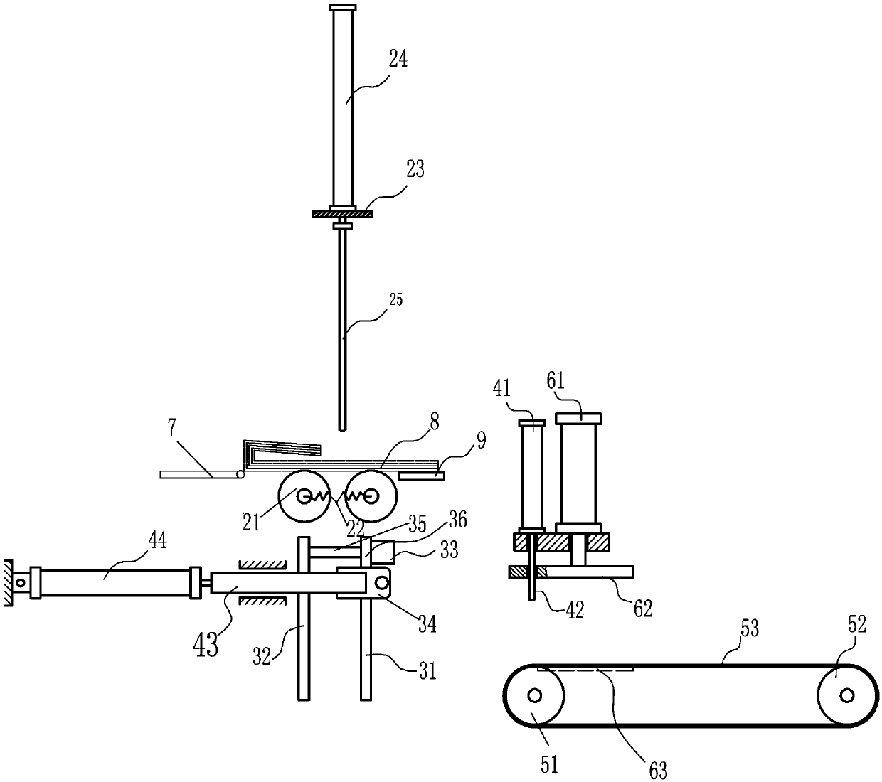
[0040] The clamping plate device 3 is arranged below the folding pinch roller 21 , and includes a fixed tooth plate 31 , a clamping tooth plate 32 , a guide rod cylinder 33 , and an overturning cylinder 34 . The fixed tooth plate 31 and the clamping tooth plate 32 include a tooth plate beam 37 and a tooth bar 38 . Both the fixed tooth plate and the clamping tooth plate can be carved with a flat plate, or a plurality of toothed bars 38 can be fixed and vertically installed on the toothed plate beam 37, and the toothed bars 38 are distributed at intervals, and there are toothed plates between the toothed bars The gap 39 forms a gap for giving way, which is convenient for the bag discharge device 4 to stretch into it and implement bag discharge (such as Figure 9 , Figure 10 shown).

[0041] The cylinder body of the guide rod cylinder 33 is fixedly installed under the middle of the tooth plate crossbeam 37 of the fixed tooth plate 31, and the guide rod cylinder end seat 36 is ...

Embodiment 2

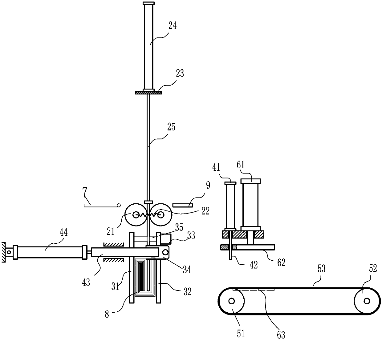
[0051] The difference from the first embodiment mainly lies in the bag discharge device and the bag discharge movement device. (Such as Figure 12 shown). The clamping plate device is directly rotated and installed on the frame 1. The bracket 43 of the bag discharge movement device and the cylinder 44 of the bag discharge movement device are installed at the rear end of the frame. A manipulator device is installed on the support 43. The clamping plate device can only be turned over Displacement, the manipulator device 45 as the bag discharging device can move relative to the clamping plate device with the bracket 43 . The overturning cylinder 34 that is installed on one end of the fixed tooth plate 31 and the other end of the fixed tooth plate are directly installed on both sides of the frame 1, and the clamping plate device can flip and swing back and forth on the frame 1; the support 43 is installed on the The rear end both sides of frame 1, between support 43 and frame 1,...


PUM


Abstract

The invention discloses a plastic folding machine which is used for folding plastic bags. The plastic bag folding machine comprises a rack, a plastic bag conveying device, a handle folding device, a final folding device, a clamping plate device, and a discharge output device. Piles of plastic bags produced on a bag making machine are conveyed to corresponding processing positions through the conveying device. Handles of the bags are folded through the handle folding device, and then the plastic bags are folded through the final folding device and are conveyed into the clamping plate device. The clamping plate device rotates 90 degrees in a swinging mode and then moves onto a bag discharge device. The bag discharge device moves downward and is inserted into clearance of the clamping plate device so as to block or pinch the plastic bags. When the clamping plate device and the bag discharge device are in relative motion, the plastic bags are discharged onto an output device. Folding package of the plastic bags is finished after manual banding. The plastic folding machine can meet requirements of diversified markets of nylon cord banding, rubber band banding or plastic film packaging, and is simple in structure and capable of folding neatly.

Description

technical field [0001] The invention relates to a folding device for a portable plastic bag. Background technique [0002] Previously, the folding and binding process of the portable plastic bags produced by the bag making machine was done manually. The applicant once applied for an invention patent with the application number "200720151993.8" and the patent name "plastic bag folding machine", publication number: CN101134377. Attempt to implement a model that only folds plastic bags without bundling, but the folded bags tend to rebound and scatter during discharge, and cannot be reliably placed in the predetermined position. Afterwards, the applicant applied for an invention patent with the patent number "201110081121.X" and the patent name "Fully Automatic Folding and Binding Machine for Plastic Bags" and obtained authorization. The publication number is CN102167172A. This patent is to automatically bundle the folded plastic bags with plastic straps in the clamping device...

Claims


Application Information

Patent Timeline
IPC IPC(8): B65B63/04B65B27/08
Inventor 王秀来
Owner 王秀来
Why Eureka
Try Eureka