Image forming apparatus

An image and paper technology, applied in the field of image forming apparatuses, can solve the problem of reducing the productivity of the image forming section 10 and the like

Active Publication Date: 2013-10-23
KONICA MINOLTA BUSINESS TECH INC
View PDF6 Cites 5 Cited by
  • Summary
  • Abstract
  • Description
  • Claims
  • Application Information

AI Technical Summary

Problems solved by technology

However, in the way of conveying and staying four sheets of paper-the surface and the back are continuously formed with images, if the interval T+surplus time β is set, the time between the paper P fed from the double-sided paper feeding path 26 to the paper adjustment section 20 will be extended. There

Method used


Image

  • Image forming apparatus
  • Image forming apparatus
  • Image forming apparatus

Examples


Embodiment Construction

[0045] Next, a configuration example, an operation example, and a control example of the image forming apparatus according to the embodiment of the present invention will be described with reference to the drawings. The description in this section does not limit the technical scope described in the claims, the meaning of terms, and the like.

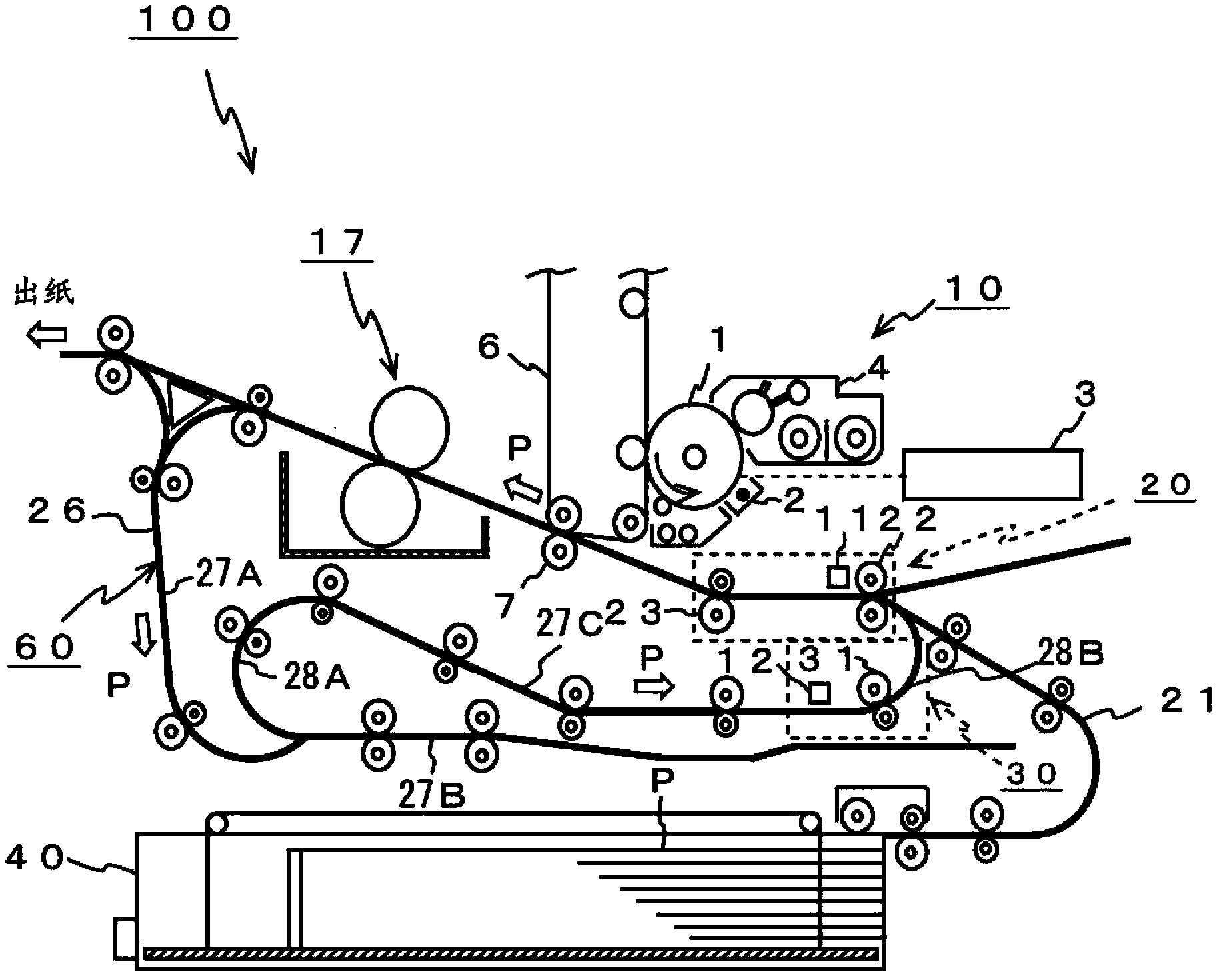
[0046] figure 1 The image forming apparatus 100 shown has a first path (hereinafter referred to as a single-sided paper path 21 ) through which paper passes in the one-sided printing mode or the like, and a first path through which the paper passes in the double-sided printing mode or the like. The second passage (hereinafter referred to as the double-sided paper feeding passage 26 ), the image forming unit 10 , the paper adjusting unit 20 , the paper conveying unit 30 , the paper feeding unit 40 and the paper turning mechanism 60 .

[0047] The single-sided paper feeding path 21 is a paper conveying path from the paper feeding unit 40...


PUM


Abstract

The control portion controls the sheet adjusting portion to alternately convey the sheet of paper fed from the sheet-feeding path for single-side printing and the sheet of paper fed from the sheet-feeding path for duplex printing to the image forming portion during the duplex printing mode. Images are alternately formed on the front surface of each of the sheets of paper and the back surface of each of the sheets of paper when three sheets of paper are conveyed to the image forming apparatus and they are left therein. The control portion controls the sheet conveying portion to release the contact of the conveying rollers after it is detected that the sheet of paper reaches the sheet adjusting portion.

Description

technical field [0001] The present invention relates to an image forming apparatus suitable for use in a color printer, a monochrome printer, a copier, or a multifunction machine having these functions. Background technique [0002] In recent years, image forming apparatuses having a double-sided printing mode for forming images on the front and back of paper have been increasingly used. Figure 8 It is a cross-sectional view showing a configuration example of a conventional image forming apparatus 200 . Figure 8 The image forming apparatus 200 shown has: a transfer unit 7, an image forming unit 10, a paper adjustment unit 20, a single-sided paper feeding path 21 through which paper passes in the single-sided printing mode, and a single-sided paper feeding path 21 in the double-sided printing mode. In other cases, the double-sided paper feeding path 26 , the paper conveying part 30 and the paper turning mechanism 60 pass through the paper. [0003] The single-sided paper fe...

Claims


Application Information

Patent Timeline
IPC IPC(8): B65H9/14B65H29/20G03G15/00
CPCB41J13/0045G03G15/6561G03G15/234
Inventor 川中子悠介大久保贵弘松尾贤广茂木春希
Owner KONICA MINOLTA BUSINESS TECH INC
Why Eureka
Try Eureka