Concrete elevation gradient controller

A concrete and controller technology, applied in the field of controllers, can solve the problems that cast-in-place concrete is difficult to meet the geometric size design requirements, cannot control the elevation and slope of the concrete surface, and the effect of concrete construction control is low, and achieves the reduction of financial and human resources. The effect of input, easy assembly, and smooth drainage

Active Publication Date: 2013-10-23
NO 1 ENG CO LTD OF CR11BG +1
View PDF6 Cites 4 Cited by
  • Summary
  • Abstract
  • Description
  • Claims
  • Application Information

AI Technical Summary

Problems solved by technology

In the existing control method, due to the limited operating space between the left and right lines of the ballastless track, large control equipment cannot be used, and only a level or a spirit level can be used to detect and control the concrete surface poured between the left and right lines of the ballastless track. These two tools are less effective in controlling the construction of concrete, and they are controlled on a point-by-point basis. They cannot effectively control the elevation and slope of the poured concrete surface, resulting in slow construction progress.
Moreover, the thickness of the concrete between the lines is relatively thin, and it is difficult for the vibrating rod to meet the geometric design requirements of the surface between the lines of the ballastless track of the railway subgrade for the cast-in-place concrete during construction.
If the cross-section and surface geometric dimensions of the concrete between the left and right lines of the ballastless track of the railway subgrade are not properly controlled, it will cause different degrees of water accumulation after the completion of the concrete construction between the left and right lines of the ballastless track of the railway subgrade, which will affect the subgrade of the ballastless track and the high-speed driving Train poses safety hazard

Method used


Image

  • Concrete elevation gradient controller
  • Concrete elevation gradient controller
  • Concrete elevation gradient controller

Examples


Embodiment Construction

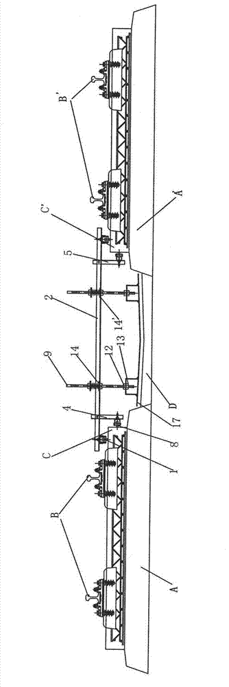
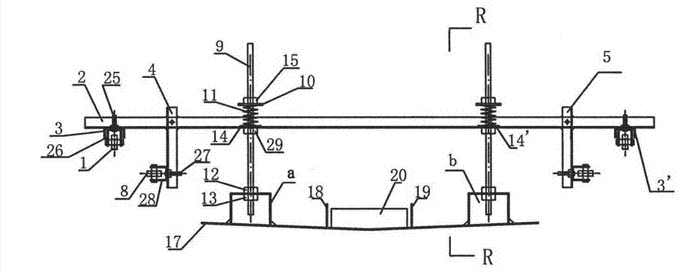
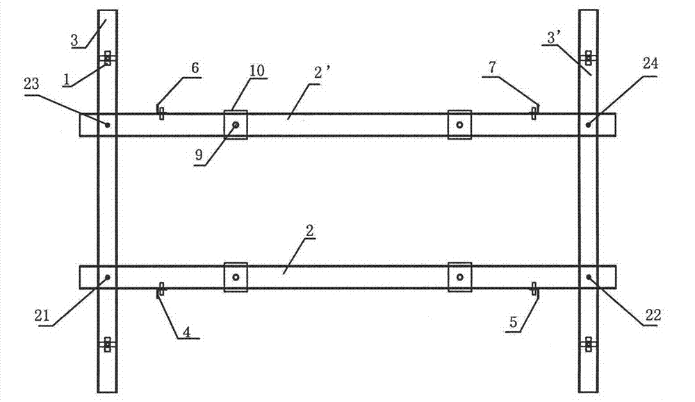
[0016] exist figure 1 , figure 2 , image 3 , Figure 4 , Figure 5 , Figure 6 In the shown embodiment, four first column seats a, second column seats b, third column seats c, fourth column seats c, and four are respectively welded on the "V" shaped vibrating steel plate 17. Column seat d; the horizontal distance between the first column seat a and the second column seat b, the third column seat c and the fourth column seat d on the "V"-shaped vibrating steel plate is 1200mm, and the vertical distance is 800mm; the height of the four columns is 850mm , diameter is 25mm elevation control column 9 lower ends and the top are provided with screw thread, with first nut 12 and second nut 13 respectively four elevation control columns are installed and fixed on the first column base a, the second column base b, the second column base On three column seats c, the 4th column seat d; With the 3rd nut 15 and the 4th nut 29 backing plate 10, damping spring 11, spring seat 14 are sl...


PUM


Abstract

The invention discloses a concrete elevation gradient controller which is characterized in that four upright seats in the same specification are welded on a V-shaped vibration steel plate; four elevation control uprights are mounted on the upright seats; backing plates, damping springs, spring seats, a first cross beam with holes and a second cross beam with holes are mounted on the elevation control uprights in a sleeving manner respectively; a first longitudinal beam and a second longitudinal beam are fastened on the undersides of the two ends of the cross beams respectively to form a rack; travelling wheel support shafts in four travelling wheel devices are mounted and fastened in holes at the two ends of the first longitudinal beam and the second longitudinal beam to form a conveying device; the upper ends of four support rods are fastened on outer walls of the first cross beam and the second cross beam by bolts respectively; limiting wheel devices are mounted at the lower ends of the four support rods; a vibration steel plate is manufactured into the V-shaped vibration steel plate; an included angle between each of two inclined planes of the V-shaped vibration steel plate and a horizontal plane is 2-8 degrees; and a vibrator is mounted and fixed between two limiting plates.

Description

technical field [0001] The invention relates to a controller, in particular to a controller for the elevation and slope of the concrete elevation and gradient of the subgrade sealing layer between the left and right lines of the ballastless railway track (passenger dedicated line). Background technique [0002] The ballastless track of the railway (passenger dedicated line) subgrade is the current development trend of the railway, and the supporting project of the ballastless track has also become the key point of construction quality control, especially the concrete sealing layer between the left and right lines of the ballastless track supporting project on the subgrade. In order to ensure the drainage between the left and right lines of the ballastless track of the railway subgrade, and to protect the railway subgrade from being penetrated by rainwater after it is formed and operated, the left and right lines of the ballastless track of the railway subgrade should be close...

Claims


Application Information

Patent Timeline
Patent Type & Authority Applications(China)
IPC IPC(8): E01B29/00
Inventor 李晓波曾国升孙本明
Owner NO 1 ENG CO LTD OF CR11BG
Why Eureka
Try Eureka