Engine oil baffle

A technology of oil baffle and circular arc plate, which is applied in the direction of mechanical equipment, engine components, machines/engines, etc., can solve the problems of not being able to play a good role in oil baffle, enhance the overall structural strength of the crankcase, and achieve the effect of oil baffle Good, easy to process, good oil blocking effect

Active Publication Date: 2013-10-23
ANHUI JIANGHUAI AUTOMOBILE GRP CORP LTD
View PDF8 Cites 1 Cited by
  • Summary
  • Abstract
  • Description
  • Claims
  • Application Information

AI Technical Summary

Problems solved by technology

[0005] The patent application number is 201020111286.8 discloses a kind of independent automobile oil pan oil baffle structure, which is located between the crankcase and the oil pan to isolate the crankshaft, and the middle part of the arched oil baffle has multiple long If the car bumps during operation, the oil in the oil pan will overflow through the long hole, which can enhance the overall structural strength of the crankcase and reduce vibration, but it cannot play a good oil retaining role.

Method used


Image

  • Engine oil baffle
  • Engine oil baffle
  • Engine oil baffle

Examples


Embodiment Construction

[0040] Specific embodiments of the present invention will be described in detail below in conjunction with the accompanying drawings.

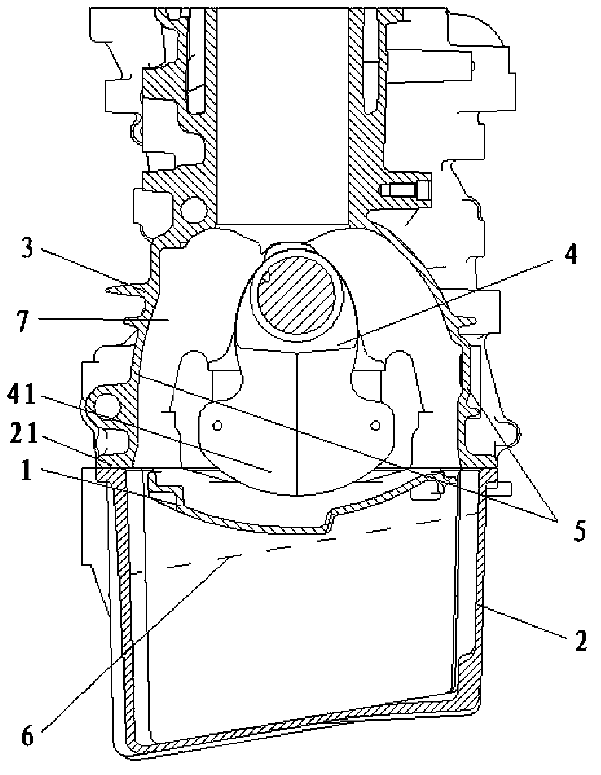
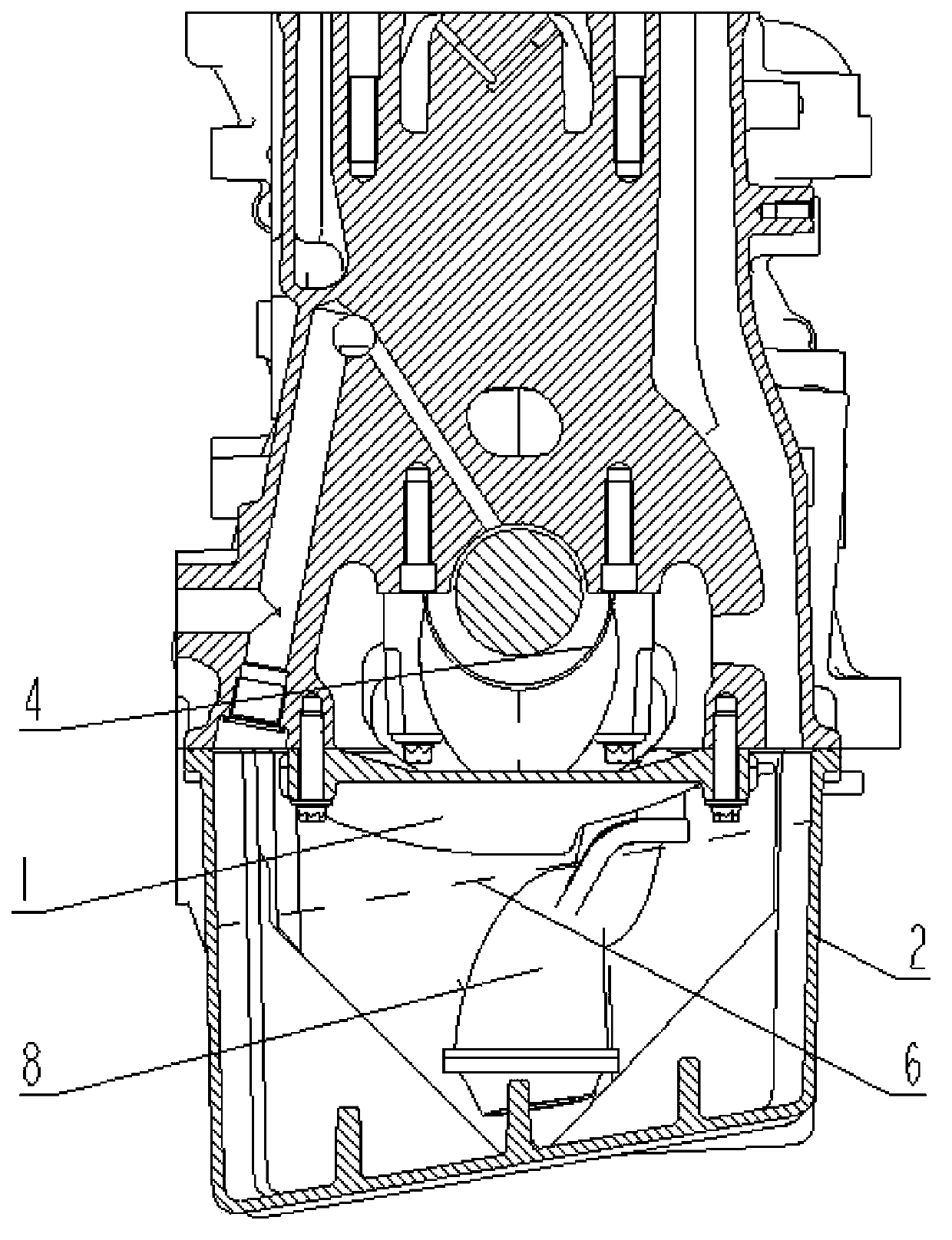
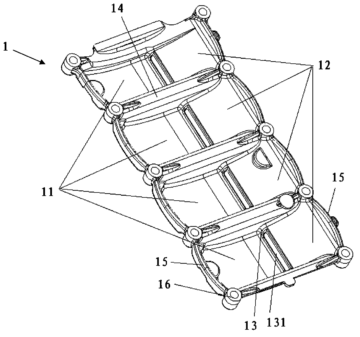
[0041] Such as figure 1 , 2 As shown, the oil baffle 1 is connected to the skirts on both sides of the upper crankcase 3, preferably to the skirts 5 on both sides of the cylinder block. It is located above the oil level 6 in the oil sump below the balance weight 41 of the crankshaft 4 and above the oil filter 8 . Specifically, the oil baffle 1 is fixed on the bottom end surface 21 of the cylinder body. The oil baffle 1 includes: a first arc plate 11 , a second arc plate 12 , and a transition plate 13 . The transition plate 13 has a strip-shaped oil drain hole 131, and the strip-shaped direction of the oil drain hole 131 is consistent with the axial direction of the crankshaft 4. The transition plate 13 connects the first arc plate 11 and the second arc plate 12, and the transition plate 13 The angle with the vertical direction is less than ...


PUM


Abstract

The invention provides an engine oil baffle which is connected to the two sides of a crank case and located below a balance block of a crank shaft. The engine oil baffle is located above an engine oil liquid level in an oil pan and an engine oil strainer. The engine oil baffle comprises a first arc slab, a second arc slab and a transition board. The transition board is provided with a strip-shaped oil drainage hole and connected with the first arc slab and the second arc slab. The oil drainage hole is located in the lowermost position of the engine oil baffle. The included angle between the transition board and the vertical direction is less than or equal to 60 degrees. The engine oil baffle has good oil blocking and returning functions and can play a good role in vibration attenuation, thereby achieving the purposes of cost reduction and light weight.

Description

technical field [0001] The invention relates to an automobile engine, in particular to an oil baffle for an automobile engine crankcase. Background technique [0002] During the operation of the vehicle, the oil in the engine oil pan will move with the bumps of the vehicle, and the sloshing oil will easily foam; at the same time, the crankshaft rotates in the crankcase, and the oil in the oil pan will be absorbed by the rotating crankshaft. Stirring will aggravate the foaming of the oil and consume the effective work of the crankshaft. If the oil shakes too violently, the oil filter will not be able to absorb the oil. [0003] Generally, the oil baffle is installed in the oil pan, and the oil baffle is completely immersed in the oil in the oil pan. Since a part of the engine oil is located above the baffle, it cannot fully play the role of oil baffle. The oil filter is installed in the oil pan, so it is necessary to open an avoidance hole on the oil baffle to install the ...

Claims


Application Information

Patent Timeline
Patent Type & Authority Applications(China)
IPC IPC(8): F01M11/00
Inventor 章家续张应兵钱多德张建操房程程李欢王宏大许涛田国庆董先瑜陈亮张亚洲
Owner ANHUI JIANGHUAI AUTOMOBILE GRP CORP LTD
Why Eureka
Try Eureka