Cooling system and method of aero-engine

An aero-engine and cooling system technology, which is applied in the cooling of the engine, engine components, turbine/propulsion device, etc., can solve the problems of airflow turbulence obstruction in the external duct, increase the difficulty of design, and increase the adjustable valve, etc., to achieve Reduce the effect of turbulence and obstruction, the effect of propulsion efficiency is small, and the effect of reducing the windward area

Active Publication Date: 2013-10-23
AECC COMML AIRCRAFT ENGINE CO LTD
View PDF8 Cites 19 Cited by
  • Summary
  • Abstract
  • Description
  • Claims
  • Application Information

AI Technical Summary

Problems solved by technology

like figure 1 As shown, the first way is to install the air-lubricating oil radiator 20' in the outer channel behind the support plate of the intermediate casing 10, and this installation method makes the air-lubricating oil radiator in the air flow of the engine outer channel Among them, it will have the effect of turbulence and hindrance to the external ducted airflow, thus affecting the propulsion efficiency of the engine to a certain extent
The second installation method is to install the air-lubricating oil radiator 20" on the outer wall of the outer ring of the intermediate case 10, and at the same time set an adjustable valve on the inner wall of the outer ring of the int

Method used


Image

  • Cooling system and method of aero-engine
  • Cooling system and method of aero-engine

Examples


Embodiment Construction

[0035] Preferred embodiments of the present invention will be described in detail below with reference to the accompanying drawings.

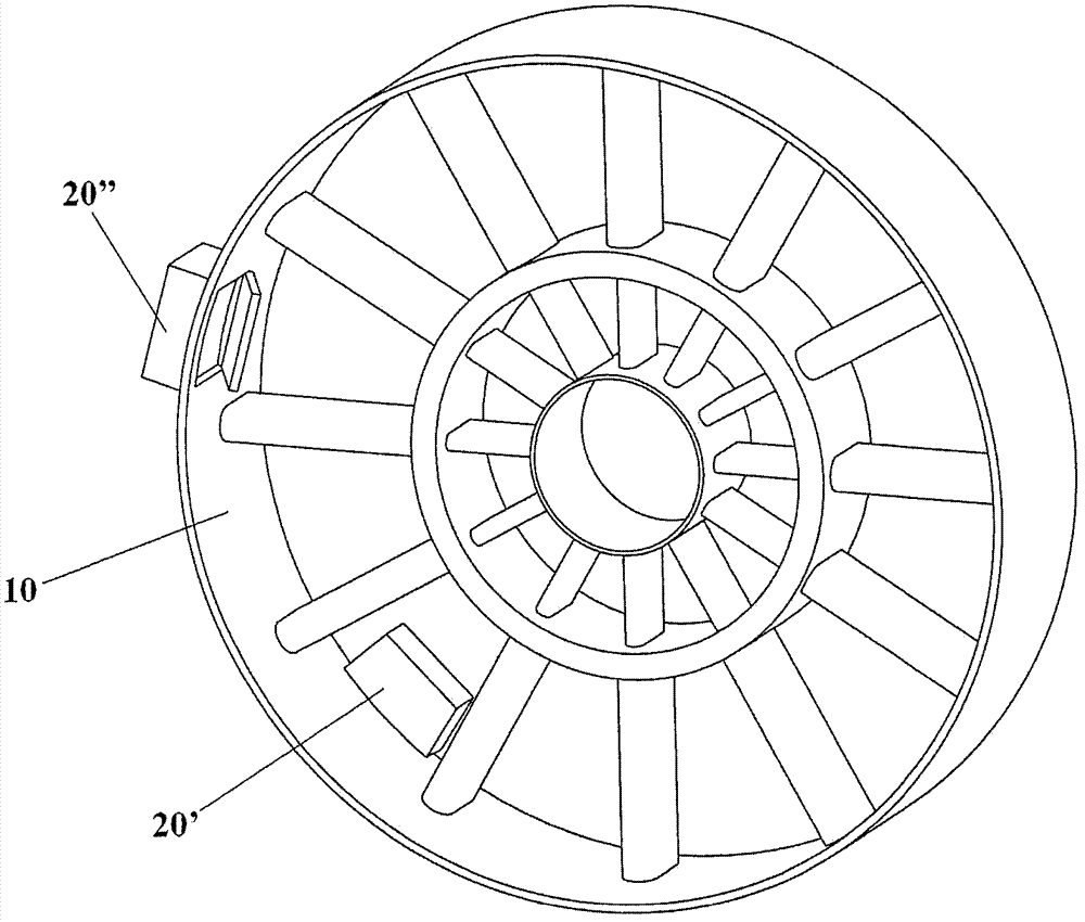
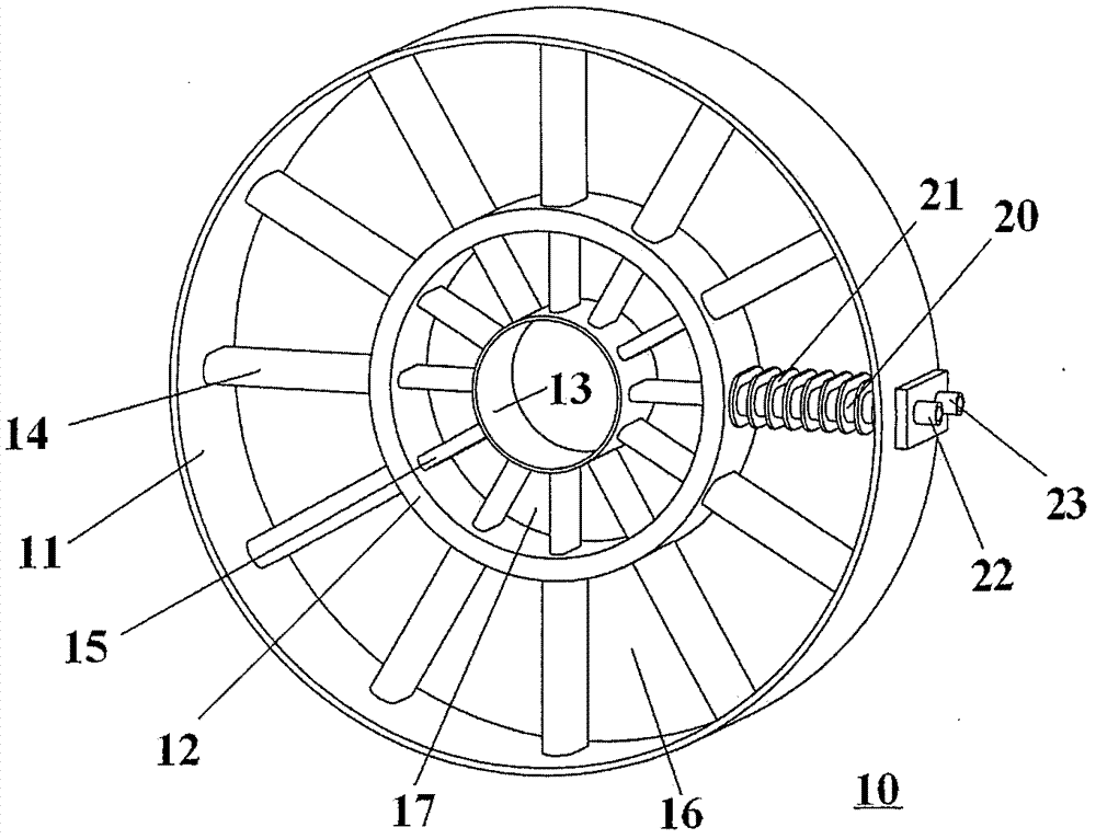
[0036] figure 2 A preferred embodiment according to the invention is shown. The air-lubricating oil cooling system according to the present invention includes an intermediate casing 10, the intermediate casing 10 is composed of an outer ring 11, a middle ring 12 and an inner ring 13, and the middle ring 12 is located between the outer ring 11 and the inner ring 13. The outer ring 11 and the middle ring 12 are connected by an outer stent strut 14 , and the middle ring 12 and the inner ring 13 are connected by an inner strut 15 . Preferably, the number of outer struts 14 and inner struts 15 is the same and their axes are on the same radius. The passage between the outer ring 11 and the middle ring 12 is the outer duct 16 , and the passage between the middle ring 12 and the inner ring 13 is the inner duct 17 . Cool air sucked in by the engine ...


PUM


Abstract

The invention provides a cooling system of an aero-engine. The cooling system comprises an intermediate case of the aero-engine, wherein the intermediate case comprises an inner ring, a middle ring and an outer ring which are sequentially increased in diameters, the inner ring is connected with the middle ring through a plurality of radially-extending inner culvert support plates, the middle ring is connected with the outer ring through a plurality of radially-extending outer culvert support plates, an air-lubricating oil heat radiator is arranged on at least one outer culvert support plate, or the at least one outer culvert support plate is replaced with the air-lubricating oil heat radiator, and the heat radiator comprises a heat radiation part as well as a lubricating oil inlet and a lubricating oil outlet which are communicated with the heat radiation part. The invention also provides a cooling method of the aero-engine, the air-lubricating oil heat radiator is arranged on the least one outer culvert support plate or the at least one outer culvert support plate is replaced with the air-lubricating oil heat radiator. According to the cooling system and method, the turbulent flow inhibition to airflows in outer culverts is reduced, and thus the influence to the propulsive efficiency of the aero-engine is reduced.

Description

technical field [0001] The invention belongs to the field of aero-engines, in particular to an aero-engine cooling system and a method thereof. Background technique [0002] The lubricating oil system is an important subsystem of the aviation turbofan engine. The heat generated by the main bearing of the engine during operation, the heat leaked from the sealed pressurized air into the bearing cavity, the heat transmitted by the wall of the bearing cavity and the pipeline wall, and the gears in the transmission The heat generated by friction is taken away by the lubricating oil, which causes the temperature of the lubricating oil to rise, so the lubricating oil must be cooled before it is used again. [0003] At present, the common lubricating oil cooling scheme for high bypass ratio turbofan engines is generally to use fuel lubricating oil radiators. The fuel oil radiator uses relatively low-temperature fuel to cool the high-temperature lubricating oil. After the fuel is he...

Claims


Application Information

Patent Timeline
IPC IPC(8): F02C7/14
Inventor 李枝东王军石志斌
Owner AECC COMML AIRCRAFT ENGINE CO LTD
Why Eureka
Try Eureka