
Pantograph head balance device

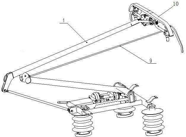
A balancing device and pantograph technology, applied in the field of pantographs, can solve problems such as greater influence on current receiving stability, unfavorable pantograph aerodynamic performance, large wind resistance, etc., to improve current receiving stability, improve Aerodynamic performance, the effect of reducing wind resistance

Active Publication Date: 2016-12-07
ZHUZHOU ELECTRIC LOCOMOTIVE CO
View PDF5 Cites 7 Cited by
  • Summary
  • Abstract
  • Description
  • Claims
  • Application Information

AI Technical Summary

Problems solved by technology

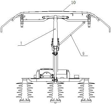
The inclined balance bar 9 is subject to greater wind resistance, which is not conducive to the aerodynamic performance of the pantograph when receiving current, especially on high-speed EMUs, which has a greater impact on the stability of receiving current

Method used


Image

  • Pantograph head balance device
  • Pantograph head balance device
  • Pantograph head balance device

Examples


Embodiment Construction

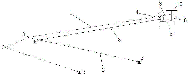
[0027] Such as Figure 3-6 As shown, a pantograph bow balance device includes a balance bar system located directly below the upper arm 1, the balance bar system includes a first bar 3 hinged to the upper end of the lower arm 2, and a first bar 3 hinged to the upper end of the upper arm 1. The second rod 4, the fourth rod 6 hinged with the bow head rotating shaft 7, the third rod 5 with one end hinged with the free end of the second rod 4 and the other end hinged with the free end of the fourth rod 6.

[0028] The first rod 3 is arranged directly below the upper arm rod 1 . The other end of the first rod 3 is hinged to the middle of the second rod 4 . The upper end of the upper arm 1 is extended with a connecting portion 8 , and the connecting portion 8 is hinged to the bow head rotating shaft 7 .

[0029] For the convenience of description, the hinge point between the lower arm 2 and the first rod 3 is E, the hinge point between the first rod 3 and the second rod 4 is J, th...


PUM


Abstract

The invention discloses a pantograph head balance device. The pantograph head balance device comprises a balance rod system located under an upper arm rod, and the balance rod system comprises a first rod hinged to the upper end of a lower arm rod, a second rod hinged to the upper end of the upper arm rod, a fourth rod hinged to a pantograph head rotating shaft and a third rod of which one end is hinged to the free end of the second rod and the other end is hinged to the free end of the fourth rod; the other end of the first rod is hinged to the middle of the second rod, the upper end of the upper arm rod extends to form a connection part, and the connection part is hinged to the pantograph head rotating shaft. According to the pantograph head balance device, a multi-connecting rod balance device with multi-sectional design is adopted to replace a traditional structure of one straight balance rod, the rotation angle of the pantograph head can remain unchanged in the rising and falling process of a pantograph, and the current collection stability is improved. Due to the fact that the balance device is arranged under the upper arm rod in a hidden mode, the windward area of the pantograph is decreased, wind resistance in high speed operation is reduced, and the aerodynamic performance of the pantograph is improved.

Description

technical field [0001] The invention belongs to pantograph technology, in particular to a pantograph head balance device. Background technique [0002] A single-arm pantograph generally consists of an underframe, a lower arm, an upper arm, a tie rod, a balance bar, and a bow head. The balance bar plays the role of balance and support, so that the angle between the bow head and the horizontal plane remains unchanged during the bow raising process. [0003] When the pantograph is raised and in contact with the network cable to receive current, due to the high running speed of the vehicle, the upper arm, lower arm, pull rod, balance bar, etc. of the pantograph will be subject to greater wind resistance, which will affect The stability of the nominal contact pressure between the Pantograph and Catenary leads to unstable flow. Therefore, when designing and manufacturing pantographs, it is hoped that the pantograph has a smaller windward area to ensure a smaller wind resistance,...

Claims


Application Information

Patent Timeline
Patent Type & Authority Applications(China)
IPC IPC(8): B60L5/20B60L5/22
CPCB60L5/20B60L5/22
Inventor 冯叶王喜亮李小亮张彦林陈明国李军张海峰陈敏坚孙宁王秋红周洁郭瑾玉
Owner ZHUZHOU ELECTRIC LOCOMOTIVE CO
Learn More