
Engine rotating speed control device of rotary drilling rig

A technology for engine speed and control devices, applied in engine control, machine/engine, electrical control, etc., can solve the problems of limited engine power, unscientific use methods, energy waste, etc., to save energy, facilitate analysis of faults, The effect of improving work efficiency

Inactive Publication Date: 2013-10-23
徐州雷曼机械科技有限公司
View PDF0 Cites 6 Cited by
  • Summary
  • Abstract
  • Description
  • Claims
  • Application Information

AI Technical Summary

Problems solved by technology

General operators often increase the engine speed to the maximum when operating the rotary drilling rig, but the actual power of the engine is limited, and a lot of power is wasted
[0003] At present, the number of foundation constructions using rotary drilling rigs in China is extremely large, and the unscientific methods of use account for the majority, resulting in serious energy waste. Diesel is a non-renewable energy source. It is necessary to use new technologies to reduce energy consumption.

Method used


Image

  • Engine rotating speed control device of rotary drilling rig

Examples


Embodiment Construction

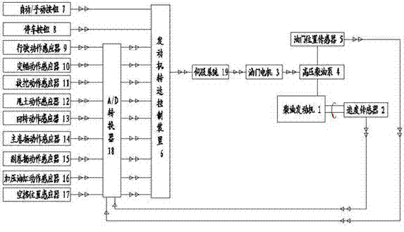
[0011] The invention includes a diesel engine 1, a speed sensor 2, an accelerator motor 3, a high-pressure diesel pump 4, an accelerator position sensor 5, an engine speed control device 6, an automatic / manual button 7, a stop button 8, a driving motion sensor 9, and a variable amplitude action Sensor 10, rotary excavation motion sensor 11, soil throwing motion sensor 12, slewing motion sensor 13, main hoist motion sensor 14, auxiliary hoist motion sensor 15, pressurized oil cylinder motion sensor 16 and neutral position The sensor 17 is connected with the A / D converter 18, and the invention is an engine speed control device 6 equipped with an automatic / manual button 7 and a parking button 8, and the engine speed control device 6 is connected with the A / D converter 18 , A / D converter 18 and driving motion sensor 9, luffing motion sensor 10, rotary digging motion sensor 11, soil throwing motion sensor 12, rotary motion sensor 13, main winch motion sensor 14, auxiliary The winch...


PUM


Abstract

The invention discloses an engine rotating speed control device of a rotary drilling rig. The engine rotating speed control device is provided with an automatic / manual button and a parking button and is connected with an A / D (analog / digital) converter and a servo system, the A / D converter is connected with a plurality of sensors, a speed sensor is fixedly mounted on a diesel engine, and an accelerator position sensor and the speed sensor are connected with the A / D converter. A working unit of the engine rotating speed control device is capable of controlling the rotating speed of the diesel engine by means of controlling an accelerator motor via a program.

Description

technical field [0001] The invention belongs to an engine speed control device, in particular to a rotary drilling rig engine speed control device. Background technique [0002] Rotary drilling rigs are widely used in various constructions such as high-rise buildings, highways, bridges, railways, ports, tunnels, and subways. become related. For example, the working states include driving, luffing, rotary excavation, soil throwing, slewing, main and auxiliary winch lifting, oil cylinder pressurization, etc. The power required for each working state is different. General operators often increase the engine speed to the maximum when operating the rotary drilling rig, but the actual power of the engine is limited, and a lot of power is wasted. [0003] At present, the number of foundation constructions using rotary drilling rigs in China is extremely large, and most of them are used unscientifically, resulting in serious energy waste. Diesel is a non-renewable energy source, s...

Claims


Application Information

Patent Timeline
Patent Type & Authority Applications(China)
IPC IPC(8): F02D45/00
Inventor 仇文宁徐伟李晓敏李丰
Owner 徐州雷曼机械科技有限公司
Learn More