Hermetic compressor and refrigerating cycle device including the hermetic compressor

A compressor and hermetic technology, which is applied in the field of refrigeration cycle devices and hermetic compressors, can solve problems such as difficulty in ensuring reliability, increased number of parts, and cost, and achieve the effect of suppressing abnormal noise

Active Publication Date: 2015-10-07
MITSUBISHI ELECTRIC CORP
View PDF2 Cites 1 Cited by
  • Summary
  • Abstract
  • Description
  • Claims
  • Application Information

AI Technical Summary

Problems solved by technology

[0006] However, in order to suppress the vibration of the compressor, in the case of a hermetic compressor that accommodates the bearings in the counterbore provided in the rotor core to achieve a low center of gravity, it is easy to adjust the pressure pulsation in the counterbore and the space above the rotor. There is a problem that the force generated by the deviation of the center of the magnet cannot suppress the abnormal sound generated by the up and down motion of the rotor.
In addition, the method of providing a spring between the bearing and the eccentric shaft of the crankshaft has the following problems. In addition to increasing the number of parts and increasing the cost, it is difficult to ensure reliability due to variations in spring force and changes over time.

Method used


Image

  • Hermetic compressor and refrigerating cycle device including the hermetic compressor
  • Hermetic compressor and refrigerating cycle device including the hermetic compressor
  • Hermetic compressor and refrigerating cycle device including the hermetic compressor

Examples


Embodiment approach 1

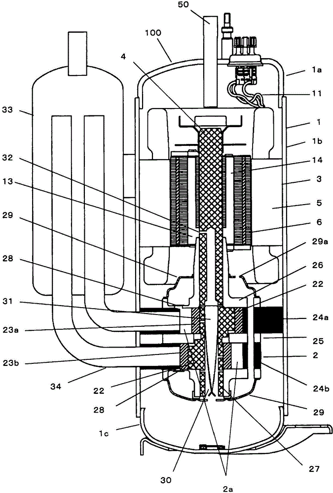
[0023] figure 1 It is a sectional view showing the hermetic compressor 100 according to Embodiment 1 of the present invention. use figure 1 The overall structure of the hermetic compressor 100 will be described. The hermetic compressor 100 will be described by taking a 2-cylinder rotary compressor as an example. The hermetic compressor 100 accommodates a compression mechanism unit 2 that compresses refrigerant and an electric element unit 3 that drives the compression mechanism unit 2 in a hermetic vessel 1 including an upper vessel 1a, an intermediate vessel 1b, and a lower vessel 1c. The compression mechanism unit 2 and the motor element unit 3 are connected by a crankshaft 4 , the compression mechanism unit 2 is housed in the lower part of the airtight container 1 , and the motor element part 3 is housed in the upper part of the airtight container 1 .

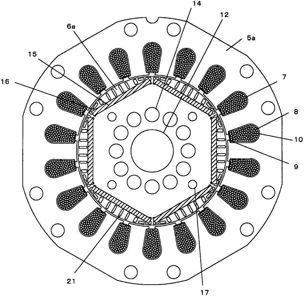
[0024] Such as figure 1 As shown, the electric element part 3 includes a stator 5 and a rotor 6, and is, for example, ...

Embodiment approach 2

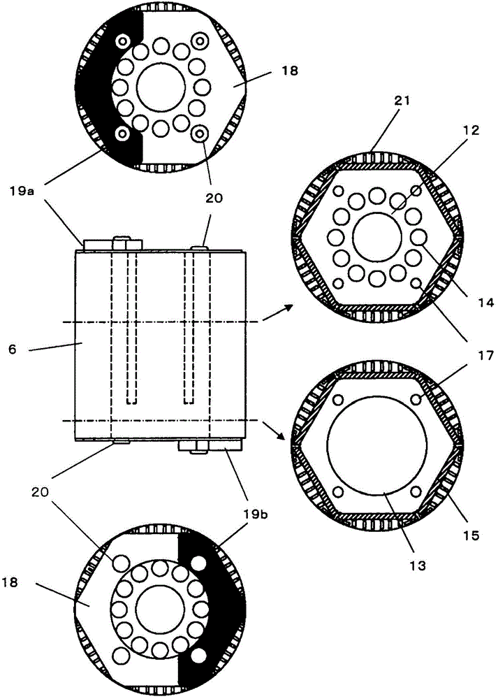
[0039] In Embodiment 1, the structure in which the generation of abnormal noise is suppressed by providing the ventilation hole 14 penetrating the rotor 6 in the counterbore portion 13 of the rotor 6 is described, but in Embodiment 2, it is necessary to prevent the leakage of the refrigerating machine oil to the outside of the compressor. When the amount of circulation is large, the structure for suppressing the amount of circulation will be described.

[0040] Figure 4 It is a structural diagram showing the rotor 6 according to Embodiment 2 of the present invention. In Embodiment 2, an opening portion 13A communicating with the ventilation hole 14 is formed on the side wall side of the counterbore portion 13 of the rotor 6 .

[0041] Figure 5 It is a schematic diagram which shows the refrigeration circuit of Embodiment 2 of this invention. The refrigerating circuit is sequentially connected to the hermetic compressor 100, the four-way switching valve 35 for switching the...

Embodiment approach 3

[0047] In Embodiment 1, the structure for suppressing the occurrence of abnormal noise was described by providing the ventilation hole 14 penetrating the rotor 6 in the counterbore portion 13 of the rotor 6. In Embodiment 2, the structure for reducing the amount of oil circulation was described. However, in Embodiment 3, a structure for suppressing the amount of oil circulation in a compressor having a structure in which the vent hole 32 provided in the crankshaft 4 is provided between the rotor 6 and the main bearing 26 will be described.

[0048] Figure 6 It is a sectional view showing the hermetic compressor 100 according to Embodiment 3 of the present invention. use Figure 6 The overall structure of the hermetic compressor 100 according to Embodiment 3 will be described.

[0049] The hermetic compressor 100 will be described by taking a single-cylinder rotary compressor as an example. The hermetic compressor 100 accommodates a compression mechanism unit 2 for compress...


PUM


Abstract

The invention provides a hermetic compressor which can inhibit abnormal sounds, low noises and low vibration generated by vertical movement of a rotor without increasing the number of parts, and a refrigeration cycle apparatus comprising the hermetic compressor. One part of a main bearing (26) of a crankshaft (4) is received inside a counter-bore part (13) of a rotor (6) of an electric element (3) which is coaxially fixed with the crankshaft (4). The rotor (6) has a vent hole (14) that is axially disposed along an upper end of the rotor (6) and is communicated with the counter-bore part (13).

Description

technical field [0001] The present invention relates to a hermetic compressor and a refrigeration cycle apparatus including the hermetic compressor. Background technique [0002] In conventional rotary hermetic compressors, in order to prevent the stator of the motor from pulsating up and down due to the influence of magnetic pulsation, the eccentric shaft of the crankshaft collides with the bearing or the intermediate plate to generate abnormal noise, by displacing the upper end surface of the rotor upward relative to the upper end surface of the stator , the center of the magnet is staggered, and a downward force always acts on the rotor (for example, refer to Patent Document 1). [0003] In addition, in order to prevent the rotor from pulsating up and down due to the difference in torque pulsation inside the compressor, the eccentric shaft of the crankshaft collides with the bearing or the intermediate plate to generate abnormal noise, and a spring is provided in the gap ...

Claims


Application Information

Patent Timeline
Patent Type & Authority Patents(China)
IPC IPC(8): F04C29/06
CPCF04C18/356F04C23/008F04C29/0021F04C29/065F04C2210/26F04C2240/40Y10S415/00Y10S417/902
Inventor 风间修谷真男中河宽行
Owner MITSUBISHI ELECTRIC CORP
Why Eureka
Try Eureka