
Voltage signal conditioning circuit of automatic reclosing lock breaker in time of electric leakage

An automatic reclosing, voltage signal technology, applied in the measurement of current/voltage, instrument, measurement of electrical variables, etc., can solve the problems of linearity not meeting the accuracy requirements, complex circuits, etc., to reduce process errors, resist temperature drift problems, The effect of linearity improvement

Inactive Publication Date: 2013-10-23
CNC ELECTRIC GRP
View PDF6 Cites 5 Cited by
  • Summary
  • Abstract
  • Description
  • Claims
  • Application Information

AI Technical Summary

Problems solved by technology

[0003] The technical problem to be solved by the present invention is that the present invention provides a leakage automatic reclosing Gate circuit breaker voltage signal conditioning circuit, the phase line of the power supply phase voltage or line voltage passes through the anode of the rectifier diode D1, the cathode of the rectifier diode D1 is connected to one end of the drop resistor R1, and also includes:

Method used


Image

  • Voltage signal conditioning circuit of automatic reclosing lock breaker in time of electric leakage
  • Voltage signal conditioning circuit of automatic reclosing lock breaker in time of electric leakage
  • Voltage signal conditioning circuit of automatic reclosing lock breaker in time of electric leakage

Examples


Embodiment Construction

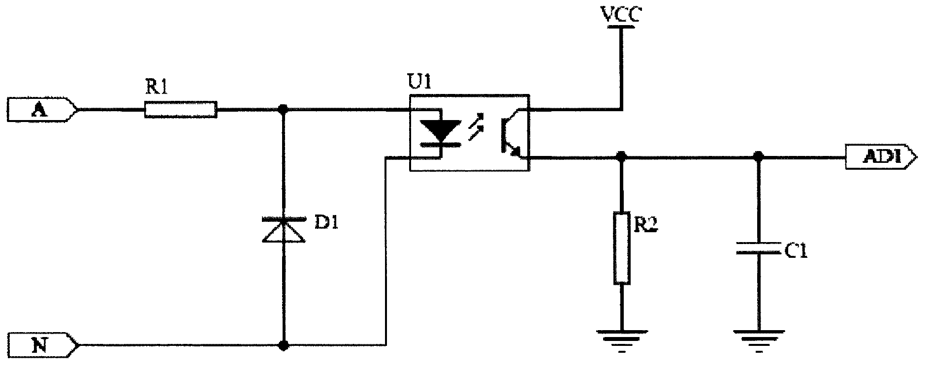
[0026] see figure 1 , figure 1 It is a voltage signal conditioning circuit with an optocoupler as the core in the prior art.

[0027] see figure 2 , figure 2 It is a voltage signal conditioning circuit with an optical coupler as the core and an operational amplifier in the prior art.

[0028] see image 3 , image 3 It is the principle diagram of the voltage signal conditioning circuit of the leakage automatic reclosing circuit breaker of the present invention. Such as image 3 Shown: the phase line of the power supply phase voltage (or line voltage) passes through the anode of the rectifier diode D1, and its neutral line (or another phase line of the line voltage) is connected to the input terminal of the phase voltage line voltage selection circuit, where the phase voltage line The voltage selection circuit is composed of resistors R2 and R3. One end of resistor R2 is connected to the neutral line of the power supply, one end of resistor R3 is connected to the other...


PUM


Abstract

The invention relates to a voltage signal conditioning circuit of an automatic reclosing lock breaker in the time of electric leakage. A phase line of power supply phase voltage or line voltage goes through the anode of a diode D1 and the cathode of the phase line is connected with one end of a resistor R1. The voltage signal conditioning circuit further comprises a phase voltage and line voltage selecting circuit, a voltage feedback circuit, a diode D2, a direct-current power supply VCC, an analog-digital converter AD1, a resistor R4 and a filter capacitor C1. A null line of the phase voltage and line voltage selecting circuit or the other phase line of the line voltage is connected with the input end of the phase voltage and line voltage selecting circuit. One end of the voltage feedback circuit is connected with the R1 and the other end of the voltage feedback circuit is connected with the phase voltage and line voltage selecting circuit. The diode D2 is connected with the voltage feedback circuit. The direct-current power supply VCC is connected with a photoelectric coupler U1a. The analog-digital converter AD1 is connected with a photoelectric coupler U1b. One end of the resistor R4 is connected with five pins of the photoelectric coupler U1b and the other end of the resistor R4 is connected to the ground. One end of the filter capacitor C1 is connected with the analog-digital converter AD1 and the other end of the filter capacitor C1 is connected to the ground. The voltage signal conditioning circuit of the automatic reclosing lock breaker in the time of electric leakage can solve the problem of temperature excursion, improve linearity and achieve common use of a three-phase three-wire system and a three-phase four-wire system.

Description

technical field [0001] The invention relates to a voltage signal conditioning circuit, in particular to a leakage automatic reclosing circuit breaker voltage signal conditioning circuit. Background technique [0002] Due to its small size, low cost and reliable isolation, optocouplers play an important role in small signal transmission circuits; in mechatronic systems integrating strong and weak electricity; in low-voltage electrical appliances equipped with embedded systems; especially It fully embodies its simple and reliable advantages in the transmission application of digital quantity and switch quantity. However, in the process of analog signal conditioning or transmission, since the semiconductor characteristics of the optocoupler are easily affected by the ambient temperature, it will cause certain nonlinear errors and drifts, which will affect the measurement and protection accuracy. At present, the commonly used solutions use temperature compensation or operationa...

Claims


Application Information

Patent Timeline
Patent Type & Authority Applications(China)
IPC IPC(8): G01R19/00G01R19/32
Inventor 余存泰赵科达夏初阳侯学强赵东杰彭昆明
Owner CNC ELECTRIC GRP
Learn More