On-line power switch cabinet monitoring system and monitoring method thereof

A technology for power switches and monitoring systems, applied in electromagnetic wave systems, non-electrical signal transmission systems, signal transmission systems, etc., can solve problems such as inability to diffract through obstructions, difficult wiring, and easy to break optical fibers, etc., to achieve enhanced reliability Scalability and security, strong anti-electromagnetic interference ability, and small power supply limitations

Active Publication Date: 2013-10-23
STATE GRID CORP OF CHINA +1
View PDF4 Cites 25 Cited by
  • Summary
  • Abstract
  • Description
  • Claims
  • Application Information

AI Technical Summary

Problems solved by technology

[0003] The current temperature measurement solutions for switchgear include color chip temperature measurement, infrared temperature measurement, optical fiber temperature measurement, active wireless temperature measurement, etc., and all have certain limitations: 1) The color chip temperature measurement method uses the color of the color chip to change Judging the temperature due to the change of the temperature, the accuracy is low, the reliability is poor, and the quantitative measurement cannot be carried out; 2) The infrared thermometer is suitable for manual inspection and temperature measurement, which is large in

Method used


Image

  • On-line power switch cabinet monitoring system and monitoring method thereof
  • On-line power switch cabinet monitoring system and monitoring method thereof

Examples


Embodiment Construction

[0038] The specific implementation manners of the present invention will be further described in detail below in conjunction with the accompanying drawings.

[0039] Aiming at the problems of large maintenance workload and high cost of the existing online monitoring system of electric switchgear, the present invention uses a wireless energy transmission device to provide power to the sensor in the form of electromagnetic radiation, and at the same time collects monitoring data in a wireless manner; the wireless sensor works in a low power consumption mode , thereby reducing the power consumption of the entire monitoring system.

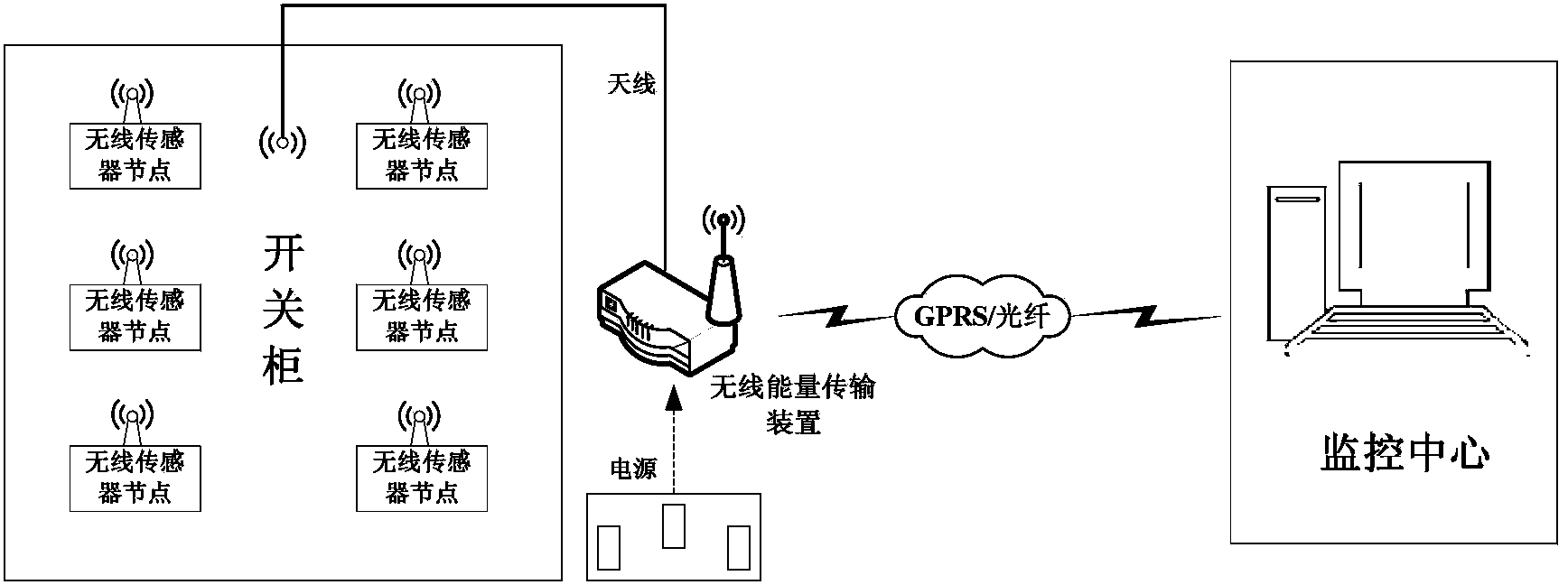
[0040] The structural diagram of the online monitoring system for power switchgear based on wireless power supply technology provided by the present invention is as follows: figure 1 As shown, including switch cabinets, wireless sensor nodes, wireless energy transmission devices and monitoring centers; where wireless sensor nodes are installed in swit...


PUM


Abstract

The invention relates to an on-line power switch cabinet monitoring system and a monitoring method thereof. The system comprises a switch cabinet, wireless sensor nodes which is installed at the parts heating easily in the switch cabinet, and a wireless energy transmission device which is installed in an instrument room of the switch cabinet or outside the switch cabinet, wherein the wireless energy transmission device conducts data interaction with a monitoring center through GPRS (General Packet Radio Service) or optical fibers. The method comprises the following steps that: the power-on wireless energy transmission device sends RF (radio frequency) energy to the wireless sensor nodes in the switch cabinet and waits restoration answering signals; the wireless sensor nodes convert electromagnetic wave energy into electric energy by utilizing RF energy collecting modules; the power-on wireless sensor nodes send the restoration answering signals to the wireless energy transmission device and provide ID numbers of the nodes; the wireless energy transmission device after receiving data sent by the wireless sensor nodes conducts local display and uploads the data to the monitoring center. According to the invention, power is supplied to sensors through an electromagnetic radiation mode, so that the characteristics of free maintenance, safety and reliability, convenience in installation and the like can be achieved.

Description

technical field [0001] The invention relates to a monitoring system and a method thereof for a power system, in particular to an on-line monitoring system and a monitoring method for a power switch cabinet. Background technique [0002] The power switchgear is an important equipment responsible for load distribution in the power system. Due to the large load current, some switchgears can pass through a current of up to 4000A for a long time, while the contact position of the contacts (plugs) in the cabinet is offset, the dynamic and static contact springs are loose, and the material Bad and other factors will lead to poor contact of the contacts, resulting in severe heat. According to the relevant requirements of the national standard GB763-1990 "Heating of AC high-voltage electrical appliances during long-term operation", the maximum allowable temperature of bare copper or bare copper alloy contacts in a 10kV switch cabinet is 75 ° C, and the maximum heating temperature of ...

Claims


Application Information

Patent Timeline
IPC IPC(8): G08C17/02G08C23/06H02J17/00H02J50/80
Inventor 盛万兴孙军平李玉凌李二霞姜建钊许保平樊勇华孙智涛
Owner STATE GRID CORP OF CHINA
Why Eureka
Try Eureka