
Waste heat recovery device

A waste heat recovery and thermoelectric technology, which is applied to electrical components, generators/motors, etc., can solve the problems of high power system requirements and achieve the effects of wide application scope, energy saving and high stability

Inactive Publication Date: 2013-10-23
EAST CHINA UNIV OF SCI & TECH
View PDF4 Cites 13 Cited by
  • Summary
  • Abstract
  • Description
  • Claims
  • Application Information

AI Technical Summary

Problems solved by technology

However, the current energy recovery method has certain requirements on the braking method, which limits the energy recovery; in addition, the current energy recovery method may change the original braking method, which has higher requirements on the power system.

Method used


Image

  • Waste heat recovery device
  • Waste heat recovery device

Examples


Embodiment Construction

[0023] The waste heat recovery device of the present invention will be further described in detail below in conjunction with the accompanying drawings.

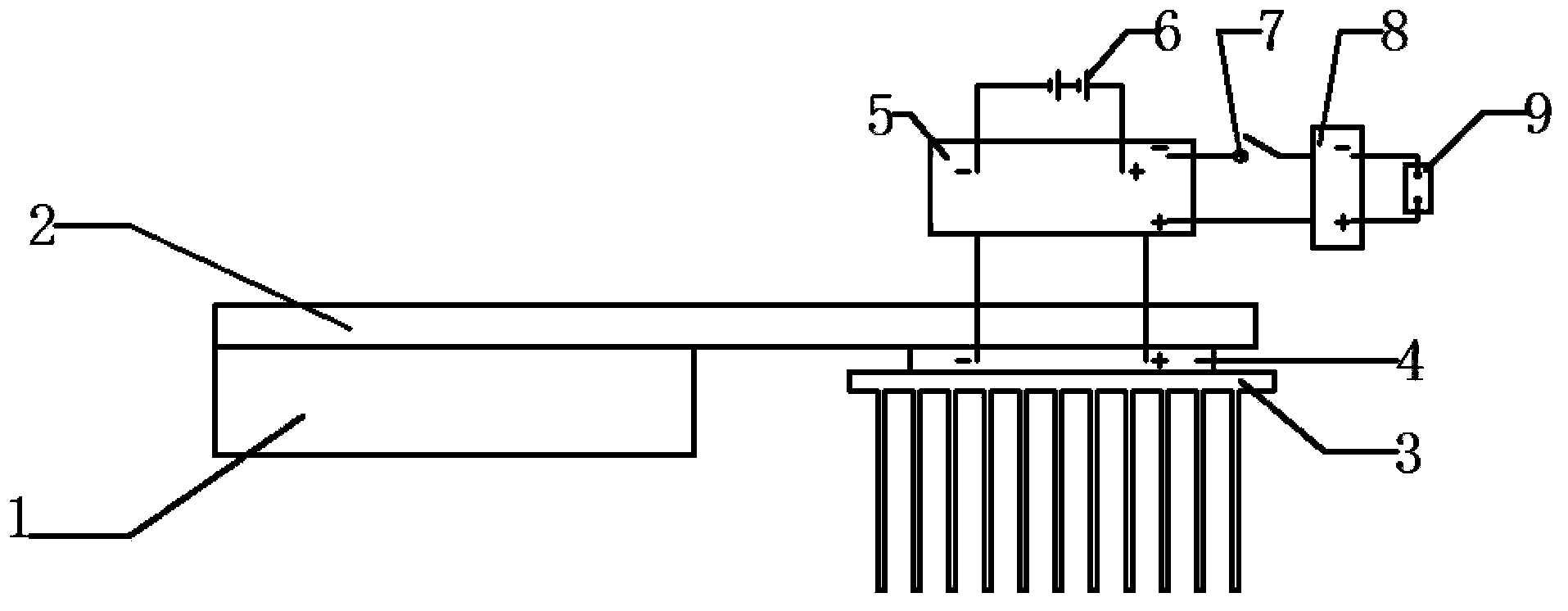
[0024] Such as figure 1 As shown, the waste heat recovery device of the present invention includes: a micro-groove flat heat pipe 2, a cooling fin 3, a thermoelectric power generation sheet 4, a charging protection circuit and a battery 6, and one end of the micro-groove flat heat pipe 2 is attached to the brake heating element 1, The other end of the micro-groove flat heat pipe 2 is in close contact with one side (hot side) of the thermoelectric generator 4, and the heat dissipation fin 3 is installed on the other side (cold side) of the thermoelectric generator 4, and the thermoelectric generator is protected by charging through electrodes The circuit is connected, and the charging protection circuit charges the storage battery 6 . Preferably, the size of the micro-grooved flat heat pipe 2 is 240mm×110mm×20mm, the size of ...


PUM

PropertyMeasurementUnit
Lengthaaaaaaaaaa
Widthaaaaaaaaaa
Heightaaaaaaaaaa

Abstract

The invention discloses a waste heat recovery device which comprises a microgroove flat plate heat pipe, radiating fins, a thermoelectric power generation piece, a charging protection circuit and a storage battery. One end of the microgroove flat plate heat pipe is attached to a brake heating piece, the other end of the microgroove flat plate heat pipe is attached to the heat side of the thermoelectric power generation piece, the radiating fins are installed on the cold side of the thermoelectric power generation piece, the thermoelectric power generation piece is connected with the charging protection circuit through an electrode, and the charging protection circuit charges the storage battery. The waste heat recovery device saves energy and protects the environment, waste heat of a brake device is recycled to generate electricity through the thermoelectric power generation technology, energy is saved, and additional pollution is not produced; the waste heat recovery device is high in stability, no moving part is arranged, the performance of the device is stable, the device is easy to maintain, and the service life is long; the waste heat recovery device can be applied to various transportation facilities with friction braking, and is wide in application range.

Description

technical field [0001] The invention relates to a braking waste heat recovery device of a transport tool, in particular to a waste heat recovery device produced by locomotive braking. Background technique [0002] In recent years, the construction of high-speed railways and urban subways in my country is in full swing. Among them, the locomotive as an operating tool will also play a greater role in future transportation and public transportation. In the environment of energy conservation and emission reduction, with the gradual expansion of locomotive operations including subways, energy problems have become more prominent, and how to effectively reduce energy consumption during locomotive operation will become increasingly important. [0003] The locomotive needs to start acceleration and braking more frequently during the short-distance operation process including subway light rail transportation, suburban transportation and short intercity transportation. In the process...

Claims


Application Information

Patent Timeline
IPC IPC(8): H02N11/00
Inventor 赵铭诚朱旭旻陶冶柳浩然王伟
Owner EAST CHINA UNIV OF SCI & TECH
Learn More