

Chaotic system method and analog circuit for automatic switching of four systems of fractional order
A chaotic system and automatic switching technology, applied in the direction of digital transmission system, transmission system, electrical components, etc., can solve the problem of less chaotic circuits, and achieve the effect of good effect, stable signal and increased randomness
- Summary
- Abstract
- Description
- Claims
- Application Information
AI Technical Summary
Problems solved by technology
Method used
Image

Examples
Embodiment 1
[0044] The method for automatically switching chaotic systems based on the fractional four systems of the Qi-type system includes the following steps:
[0045] (1) According to Qi chaotic system I:
[0046]
[0047] (2) According to the Qi type chaotic system II:
[0048]
[0049] (3) Construct symbolic functions III and IV according to the chaotic system as:
[0050]
[0051]
[0052] (4) According to the Qi chaotic system V:
[0053]
[0054] (5) According to the Qi chaotic system VI:
[0055]
[0056] (6) According to the chaotic system, the selection function VII is:
[0057]
[0058] (7) According to the system I, II, V, VI and the selection function VII, construct a Qi-type four systems to automatically switch the chaotic system IX as:
[0059]
[0060] (8) Construct a Qi-type fractional order four systems automatically switch chaotic system X according to system IX:
[0061]
[0062] (9) Construct an analog circuit system according to the chaotic system X, and use a voltage comparato...
Embodiment 2
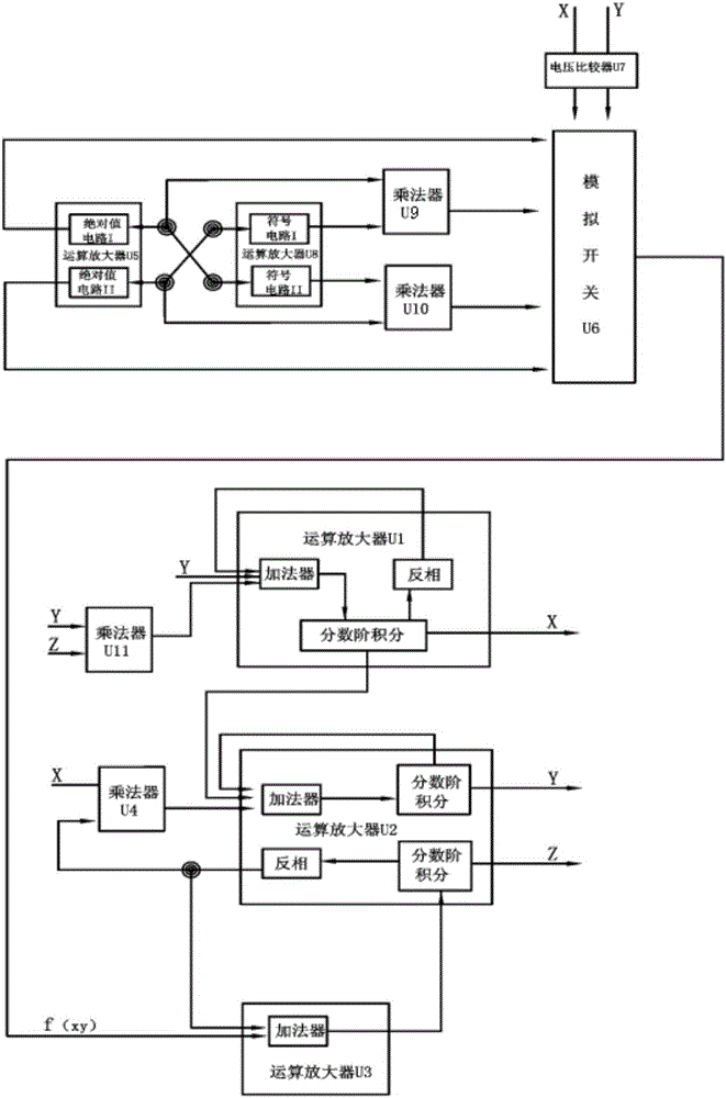
[0064] Such as figure 1 As shown, an analog circuit for implementing the above method includes an operational amplifier U1, an operational amplifier U2, an operational amplifier U3, an operational amplifier U5, an operational amplifier U8, a multiplier U4, a multiplier U9, a multiplier U10, a multiplier U11, and a voltage The comparator U7 and the analog switch U6. The operational amplifier U1 is connected to the voltage comparator U7, the operational amplifier U5, the operational amplifier U8, the multiplier U4, and the operational amplifier U2. The operational amplifier U2 is connected to the operational amplifier U1, the operational amplifier U5, and the voltage Comparator U7, operational amplifier U8, said operational amplifier U3 is connected to operational amplifier U2 and multiplier U4, said operational amplifier U5 is connected to analog switch U6, said voltage comparator U7 is connected to analog switch U6, and said operational amplifier U8 is connected to operational A...
Embodiment 3
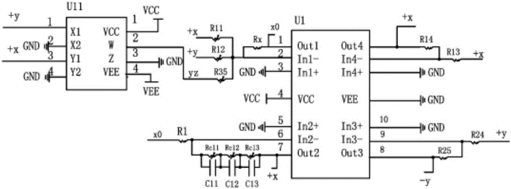
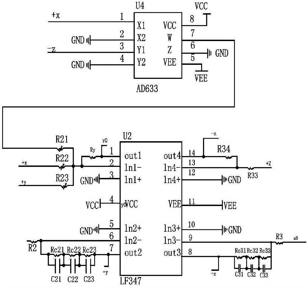
[0071] Such as Figure 2-Figure 6 As shown, the specific circuit is:
[0072] The first pin of the operational amplifier U1 is connected to the second pin through a resistor Rx, and the sixth pin is connected through a resistor R1, and the third, fifth, tenth, and twelfth pins are grounded , The 4th pin is connected to VCC, the 11th pin is connected to GND, the 6th pin is first connected to the parallel connection of resistor Rc11 and capacitor C11, then the parallel connection of resistor Rc12 and capacitor C12, and then the parallel connection of resistor Rc13 and capacitor C13 The seventh pin, the seventh pin is connected to the 13th pin through the resistor R13, the second pin of U2 through the potentiometer R22, the first pin of U4, the second pin of U5 through the resistor Ra1, then The fifth pin of U7 is connected to the second pin of U8 and the first pin of U9. The eighth pin is connected to the ninth pin through a resistor R25. The thirteenth pin is connected to the fou...
PUM
 Abstract
Description
Claims
Application Information