Method for compensating local lens shadow

A technology of lens shading and compensation method, applied in image data processing, instruments, electrical components, etc., can solve problems such as image color cast

Active Publication Date: 2013-10-23
NOVATEK MICROELECTRONICS CORP
View PDF4 Cites 20 Cited by
  • Summary
  • Abstract
  • Description
  • Claims
  • Application Information

AI Technical Summary

Problems solved by technology

[0004] The invention relates to a local lens shadow compensation method, which can correct t

Method used


Image

  • Method for compensating local lens shadow
  • Method for compensating local lens shadow
  • Method for compensating local lens shadow

Examples


Embodiment Construction

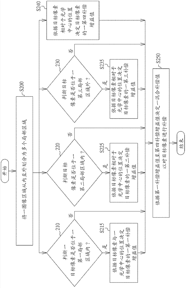
[0025] The local lens shading compensation method proposed by the present invention divides the image area into multiple local areas and compensates with different compensation gain values, so the shading condition of the image processing device can be corrected, and the problem of image color shift can be solved.

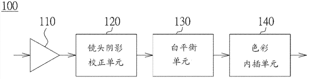
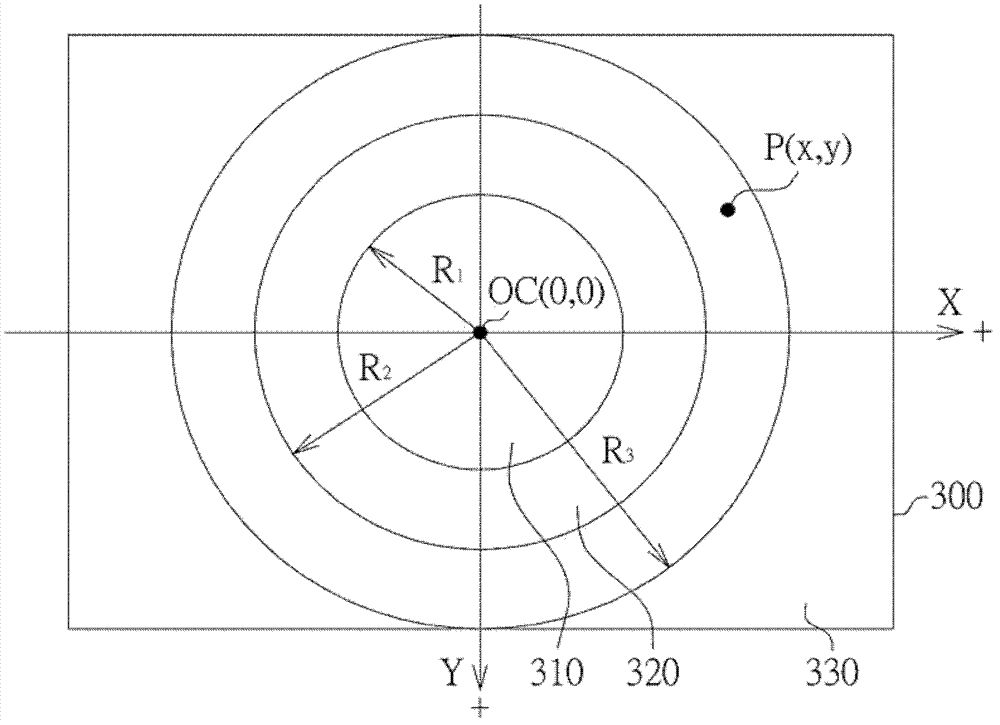
[0026] Please refer to figure 1 , which is a block diagram of an image processing device according to an embodiment. The image processing device 100 includes an analog-to-digital converter 110 and a lens shading correction unit 120 . The analog-to-digital converter 110 receives a plurality of pixel voltages of an image area from a pixel array, and converts them into a plurality of digital pixel data. The lens shading correction unit 120 generates a mixed compensation value according to an individual position of a target pixel to compensate the target pixel. Each local area is centered on an optical center of the image area. In addition, the image processing devi...


PUM


Abstract

The invention relates to a method for compensating local lens shadow. An image region is divided into a plurality of local regions from inside out by taking an optical center as a centre point. When a target pixel is located in a first local region, a first compensation gain value is determined according to the position of the target pixel relative to the optical center; when the target pixel is located in a second local region, a second compensation gain value is determined according to the position of the target pixel relative to the optical center; when the target pixel is located in a third local region, a third compensation gain value is determined according to the position of the target pixel relative to the optical center; when the target pixel is located in a fourth local regions, a fourth compensation gain value is determined according to the position of the target pixel relative to the optical center; and a mixed compensation value is determined according to the first compensation value to the fourth compensation value so as to carry out compensation on the target pixel.

Description

technical field [0001] The invention relates to a compensation method for partial lens shadow. Background technique [0002] Image sensors are usually made up of an array of photosensitive diodes (photodiodes) called pixels. The pixels themselves do not extract color from light, but instead convert photons in a broad spectrum into electrons. In order to record a color image with a single sensor, the sensor must have color filters to filter the light so that different pixels receive different colors. Different color filters are arranged on the sensor according to predetermined patterns, and the most commonly used pattern is Bayer pattern, but not limited thereto. In Bell mode, half of the total number of pixels are green (G), while a quarter of the total are red (R), and the remaining quarter are blue (B). To obtain the color message, red, green and blue color filters are arranged in a specific order to form a repeating pattern. Bell patterns consist of 2×2 arrays. [00...

Claims


Application Information

Patent Timeline
IPC IPC(8): H04N1/58G06T5/00
Inventor 徐纬
Owner NOVATEK MICROELECTRONICS CORP
Why Eureka
Try Eureka