A polarization module and a display panel

A display panel and polarizing technology, applied in optics, optical components, nonlinear optics, etc., can solve problems such as color shift of display panels

Active Publication Date: 2018-12-21
BOE TECH GRP CO LTD +1
View PDF6 Cites 11 Cited by
  • Summary
  • Abstract
  • Description
  • Claims
  • Application Information

AI Technical Summary

Problems solved by technology

[0004] In order to solve the above technical problems, an embodiment of the present invention provides a polarizing module and a display panel, which solves the problem of different viewing angles of t

Method used


Image

  • A polarization module and a display panel
  • A polarization module and a display panel
  • A polarization module and a display panel

Examples


Embodiment Construction

[0039] In order to make the purpose, technical solution and advantages of the present invention more clear, the embodiments of the present invention will be described in detail below in conjunction with the accompanying drawings. It should be noted that, in the case of no conflict, the embodiments in the present application and the features in the embodiments can be combined arbitrarily with each other.

[0040] The steps shown in the flowcharts of the figures may be performed in a computer system, such as a set of computer-executable instructions. Also, although a logical order is shown in the flowcharts, in some cases the steps shown or described may be performed in an order different from that shown or described herein.

[0041] The following specific embodiments provided by the present invention can be combined with each other, and the same or similar concepts or processes may not be repeated in some embodiments.

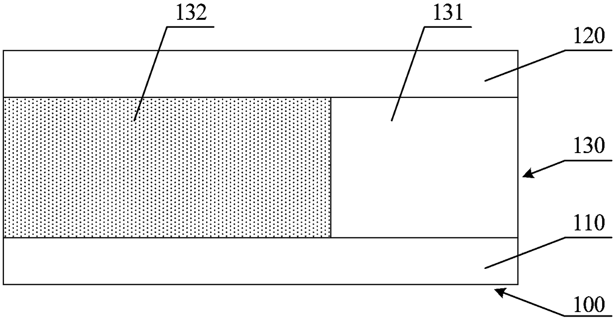
[0042] figure 1 A schematic structural diagram of a pola...


PUM

PropertyMeasurementUnit
Thicknessaaaaaaaaaa

Abstract

The embodiment of the invention discloses a polarization module and a display panel. The polarization module comprises a first polarizing plate arranged on the light entrance side and a second polarizing plate arranged on the light exit side, and a polarizing film layer arranged between the first polarizing plate and the second polarizing plate, wherein the polarizing film layer comprises a lighttransmitting region and a polarizing region; A first polarizer and a second polarizer are used for emitting incident polarized light as linearly polarized light in a specified polarization direction;A polarizing region is used for retarding a phase of linearly polarized light incident into the polarizing region in a direction different from an optical axis direction of the polarizing region suchthat the exiting polarized light includes a first polarized light in a first polarizing direction and a second polarized light in a second polarizing direction; A light-transmitting region is used fortransmitting light incident into the light-transmitting region. The embodiment of the invention solves the problem of color deviation of the existing display panel under different viewing angles without affecting the front efficiency of the OLED panel, the cathode resistance and the color gamut of the display picture.

Description

technical field [0001] This application relates to but not limited to the field of display technology, especially a polarizing module and a display panel. Background technique [0002] With the rapid development of display lighting technology, while the existing display panel meets the individual needs of users, it also exposes some problems. Among them, the color deviation of the white screen under different viewing angles is particularly obvious, which has seriously affected the user's viewing. experience. [0003] At present, the color shift problem of Organic Electroluminance Display (OLED) panels can be improved by adjusting the thickness of the cathode and weakening the microcavity effect, but it will reduce the front efficiency and increase the cathode resistance. question. In addition, the color shift of the OLED panel can also be improved by adjusting the position of the microcavity to strengthen the wavelength band, but the color gamut of the display screen will ...

Claims


Application Information

Patent Timeline
IPC IPC(8): H01L27/32G02B27/28
CPCG02B27/286H10K59/10G02B5/3083G02B5/305G02F1/133631G02F1/133638G02F1/133514G02F2202/022G02F1/13363G02F1/133528G02F1/133531G02F1/133541C09K2323/03H10K50/868H10K59/353
Inventor 周威龙
Owner BOE TECH GRP CO LTD
Why Eureka
Try Eureka