

Imaging apparatus, imaging method, and camera system
An imaging device and imaging technology, applied in parts of TV systems, image communication, TV, etc., can solve problems such as difficult to determine the color of the subject
- Summary
- Abstract
- Description
- Claims
- Application Information
AI Technical Summary
Problems solved by technology
Method used
Image

Examples
no. 1 example
[0036] [Example of the configuration of the entire camera system]
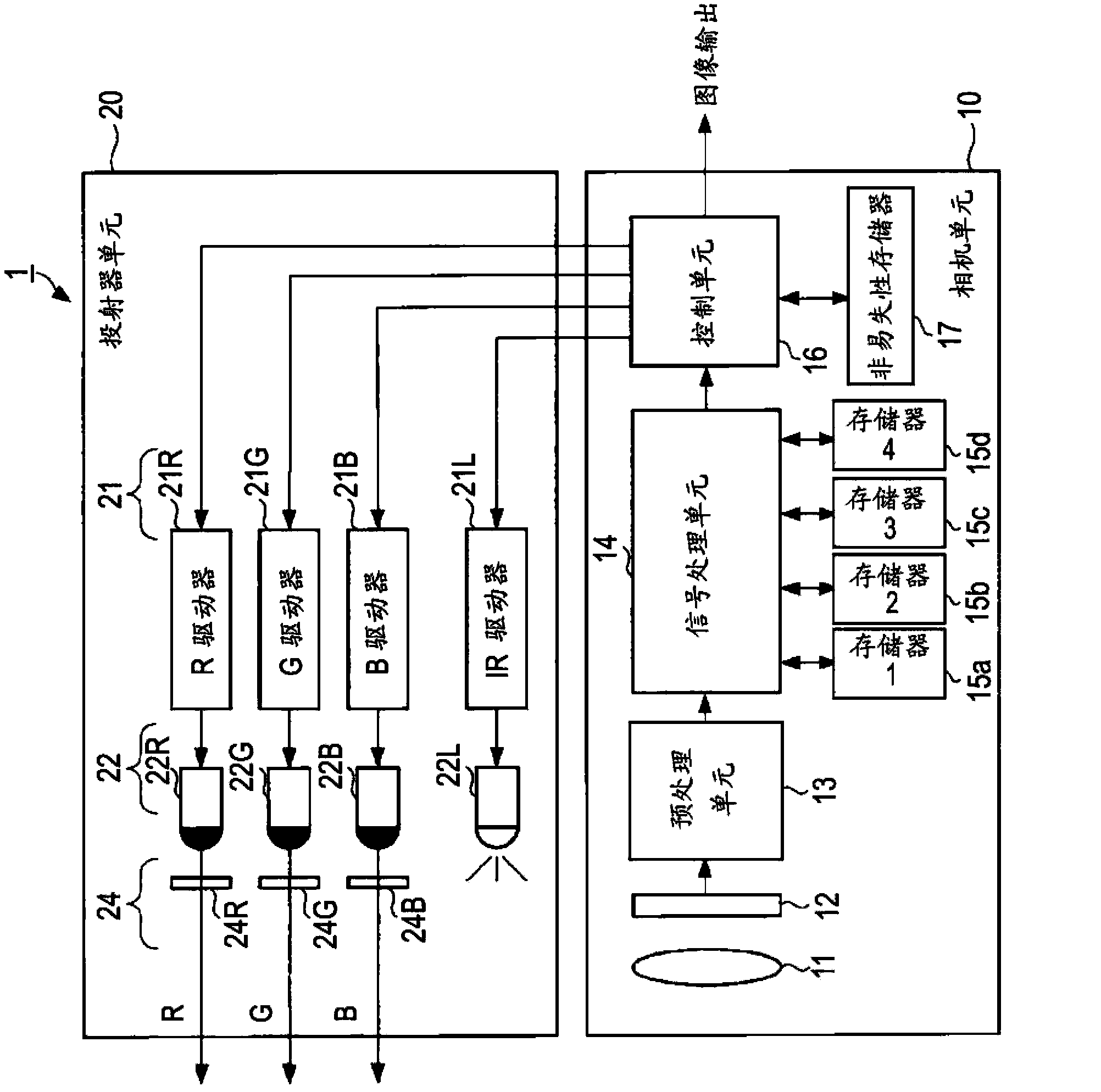
[0037] figure 1 is a block diagram illustrating an example of the configuration of the camera system according to the first embodiment of the present disclosure.
[0038] A camera system 1 according to an example of this embodiment includes a camera unit 10 (an example of an imaging device) and a projector unit 20 . Like a general camera, the camera unit 10 includes, for example, a lens 11 , an imaging device 12 , a preprocessing unit 13 , a signal processing unit 14 , a control unit 16 , and a nonvolatile memory 17 .
[0039] The lens 11 collects light rays from a subject, and forms an image on an imaging surface of the imaging device 12 . The imaging device 12 is an image sensor such as, for example, a charge-coupled device (CCD) in which pixels each having a photoelectric conversion device for performing photoelectric conversion are arranged two-dimensionally, and is provided with For example, a color se...
no. 2 example
[0109] In the first embodiment, as means for extracting color information about each pixel of an infrared image from a color image, the infrared image is region-divided, and the reflected light of the laser pattern of the pixel of interest in the closest region is referred to Strength of. The second embodiment shows an example in which a color image is reduced and color information is extracted using only the reduced color image. Here, reduction in the number of pixels to configure an image is referred to as image reduction.
[0110] Figures 10A to 10C is an explanatory diagram illustrating processing for extracting color information using a reduced image according to the second embodiment of the present disclosure.
[0111] First, the color image acquisition unit 14 c (an example of an image reduction unit) performs processing for averaging pixel values of a plurality of pixels 41 arranged in a matrix using a plurality of adjacent pixels for the captured color image 40A....
no. 3 example
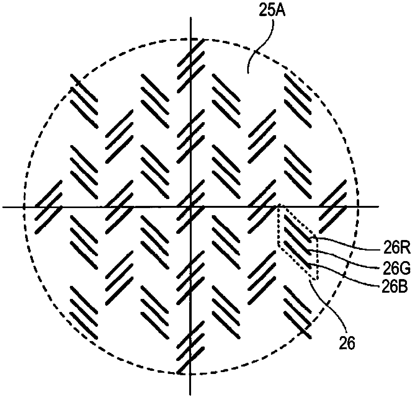
[0118] In the first and second embodiments, a fixed pattern is used as the laser pattern projected when capturing a color image. However, in the third embodiment, it is possible to extract colors from the entire screen by performing an operation of scanning a laser pattern.
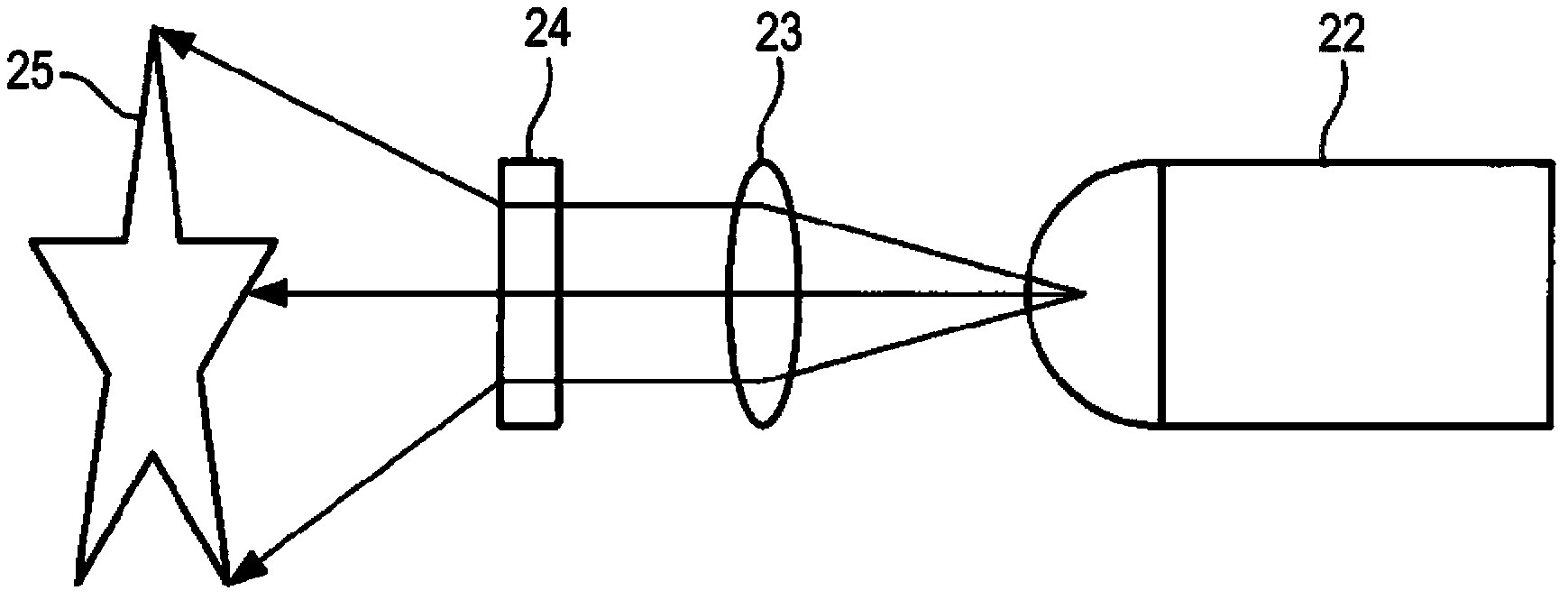
[0119] Figure 11 is an explanatory diagram illustrating a camera system that extracts color from the entire screen by scanning a laser pattern over the entire viewing angle area according to the third embodiment of the present disclosure. in addition, Figure 12 is a configuration diagram illustrating an example of a projector unit according to a third embodiment of the present disclosure.
[0120] Such as Figure 11 As shown, the camera system according to the third embodiment includes at least a projector unit 51 , a polygonal mirror 52 (an example of a scanning unit), and a camera unit 10 . Figure 11 The description of the camera unit 10 is omitted in . other configurations with figure 1 The co...
PUM
 Abstract
Description
Claims
Application Information