Piezoelectric bone conduction receiver and portable electronic equipment

A receiver and bone conduction technology, applied in the field of receivers, can solve problems such as weakening, insufficient reproduction of low-frequency areas, and high mechanical quality factor of the vibration system, and achieve the effects of increasing volume and good call privacy

Active Publication Date: 2013-10-23
GUANGDONG OPPO MOBILE TELECOMM CORP LTD +1
View PDF5 Cites 24 Cited by
  • Summary
  • Abstract
  • Description
  • Claims
  • Application Information

AI Technical Summary

Problems solved by technology

[0011] The piezoelectric bone conduction device proposed by the patent CN1627864A has high impedance and high input voltage, and the resonance frequency is high, so that the reproduction of the low frequency region is insufficie

Method used


Image

  • Piezoelectric bone conduction receiver and portable electronic equipment
  • Piezoelectric bone conduction receiver and portable electronic equipment
  • Piezoelectric bone conduction receiver and portable electronic equipment

Examples


Embodiment Construction

[0035] The present invention will be further described below with reference to the accompanying drawings and in combination with preferred embodiments.

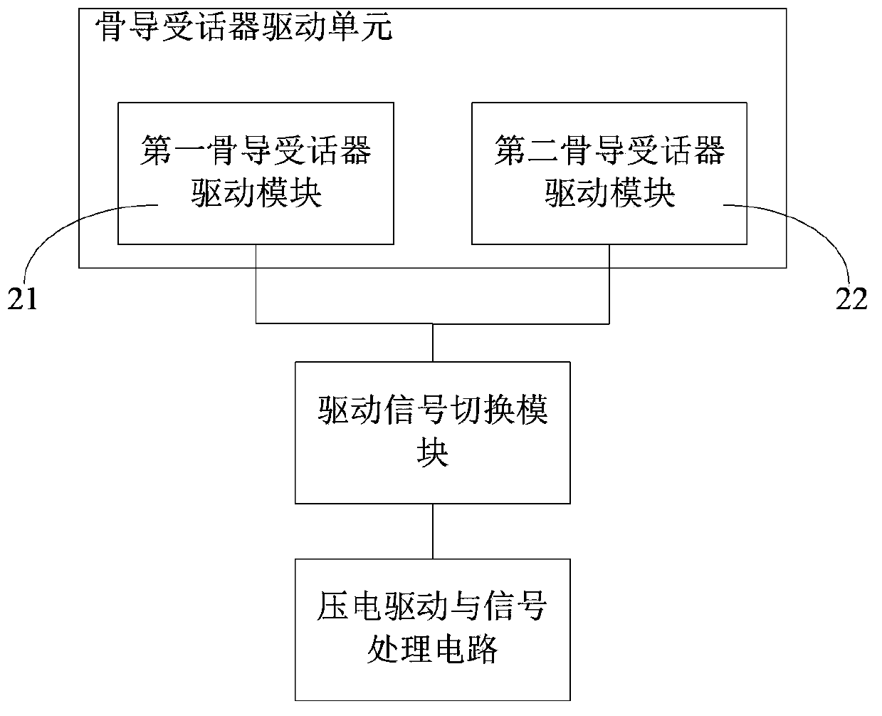
[0036] Such as figure 1 As shown, a piezoelectric bone conduction receiver includes: a piezoelectric bone conduction receiver drive unit as an acoustic vibration element, and a piezoelectric drive and signal processing circuit connected to the piezoelectric bone conduction receiver drive unit, and also includes a drive Signal switching module;

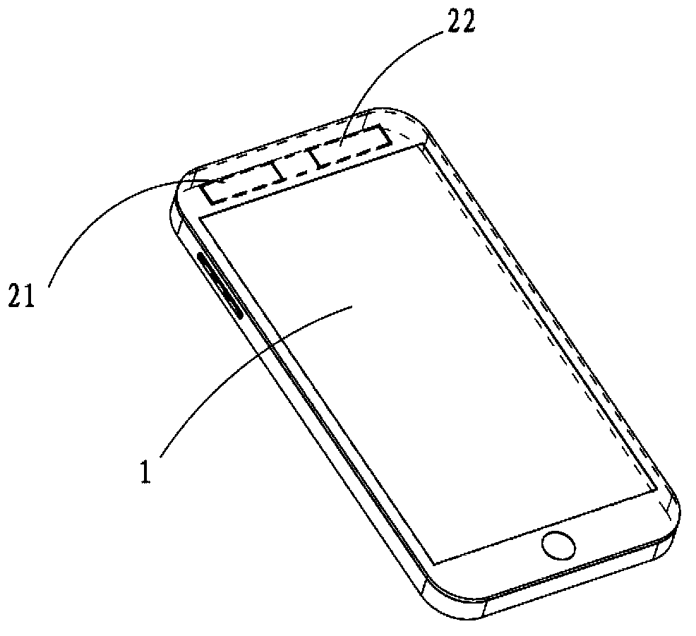
[0037] The piezoelectric bone conduction receiver drive unit includes at least two piezoelectric bone conduction receiver drive modules that can be driven independently. In this embodiment, it includes a first piezoelectric bone conduction receiver drive module 21 and a second bone conduction receiver drive module 22;

[0038] The two piezoelectric bone conduction receiver drive modules are respectively connected to the drive signal switching module, and the drive signal switching mo...


PUM


Abstract

The invention discloses a piezoelectric bone conduction receiver and portable electronic equipment. The piezoelectric bone conduction receiver comprises a piezoelectric bone conduction receiver driving unit serving as an acoustic vibration element and a piezoelectric driving and signal processing circuit connected with the piezoelectric bone conduction receiver driving unit, and further comprises a driving signal switching module; the piezoelectric bone conduction receiver driving unit at least comprises two piezoelectric bone conduction receiver driving modules which can perform driving independently; the piezoelectric bone conduction receiver driving modules are connected with the driving signal switching module respectively; the driving signal switching module is connected with the piezoelectric driving and signal processing circuit and is used for controlling the phases of piezoelectric driving signals output by the piezoelectric driving and signal processing circuit to the piezoelectric bone conduction receiver driving modules, so that the phases of the piezoelectric driving signals received by the piezoelectric bone conduction receiver driving modules are identical or opposite. The piezoelectric bone conduction receiver has the benefit of improving call privacy.

Description

technical field [0001] The invention relates to a receiver, in particular to a piezoelectric bone conduction receiver and a portable electronic device. Background technique [0002] With the popularity of smart phones, the screens of current mobile phones are getting bigger and bigger, and the phones are getting thinner and thinner. Due to the complex structure of the traditional dynamic receiver (that is, earpiece), it is difficult to realize miniaturization and thinning. Moreover, since the working principle of the traditional dynamic receiver is that the diaphragm pushes the air to vibrate to produce sound, openings for air conduction must be reserved in the application structure design, which destroys the appearance of the entire device and is prone to the hidden danger of dust or moisture entering the device . [0003] The local sound pressure of the air-conducted receiver is usually about 90-100dB when it is working. In a quieter surrounding environment (such as a ge...

Claims


Application Information

Patent Timeline
IPC IPC(8): H04R17/00H04M1/03
CPCH04R17/00H04M1/03H04R3/12H04R2460/13H04R2499/11
Inventor 严笔祥袁世明
Owner GUANGDONG OPPO MOBILE TELECOMM CORP LTD
Why Eureka
Try Eureka