
Cell reselection method and user equipment

A technology for user equipment and cell reselection, applied in the field of wireless communication, can solve problems such as increased UE power consumption, UE inability to attach/update location, and affect user experience, so as to reduce power consumption, improve user experience, and avoid ping-pong effects Effect

Inactive Publication Date: 2013-10-23
ZTE CORP
View PDF3 Cites 10 Cited by
  • Summary
  • Abstract
  • Description
  • Claims
  • Application Information

AI Technical Summary

Problems solved by technology

[0019] During the research and practice of the existing technology, it is found that the existing technology has the following problems: the PS backoff timer is running, there is no CS backoff timer, the service of the UE in GERAN / UTRAN ends, the UE returns to the idle mode, and the normal cell resumption is adopted. If selected, the UE may reselect back to the E-UTRAN cell, but the PS back-off timer in E-UTRAN is still running, and the UE cannot initiate attach / location update in E-UTRAN, which may occur in GERAN / UTRAN and E-UTRAN - Ping-pong effect between UTRANs, resulting in increased UE power consumption and affecting user experience

Method used


Image

  • Cell reselection method and user equipment
  • Cell reselection method and user equipment
  • Cell reselection method and user equipment

Examples


Embodiment 1

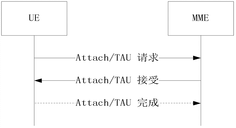
[0081] The scenario of this embodiment is: the UE sends a joint attach request to the network side, such as Figure 5 shown, including the following steps:

[0082] In step 201, the UE sends a joint attach request message to the network side.

[0083] The combined attachment includes: EPS service attachment and non-EPS service attachment, or EPS service attachment and SMS only attachment;

[0084] The network side refers to the MME.

[0085]Step 202, the network side sends a rejection response message to the UE, and indicates in the message that the reason is congestion;

[0086] The response message is an attach reject (attach reject) message;

[0087] The attach reject means that both EPS and non-EPS attachments fail;

[0088] The congestion indication includes a backoff timer, and the T3346 is a PS backoff timer, indicating PS congestion.

[0089] Step 203, whether T3246 is running, if yes, go to step 204, otherwise go to step 205.

[0090] The T3246 is the back-off t...

Embodiment 2

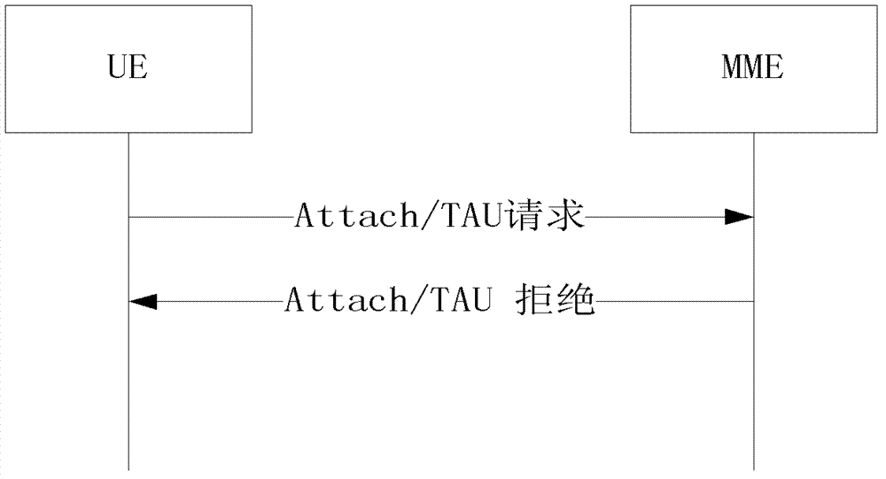
[0108] The scenario of this embodiment is: the UE sends a joint location update request to the network side, such as Figure 6 shown, including the following steps:

[0109] Step 301, the UE sends a joint location update request in E-UTRAN;

[0110] The joint location update includes: TAU and LAU;

[0111] Step 302, the network side sends a rejection response message to the UE, and indicates in the message that the reason for the rejection is congestion;

[0112] The response message is a TAU reject message;

[0113] The TAU reject means that both EPS TAU and non-EPS location updates fail;

[0114] The congestion indication includes a T3346 backoff timer, and the T3346 is a PS backoff timer, indicating PS congestion.

[0115] Step 303, whether T3246 is running, if yes, go to step 304, otherwise go to step 305.

[0116] The T3246 is the back-off timer of the CS, that is, the running of the T3246 indicates that the CS is congested.

[0117] In step 304, the UE camps in the...


PUM


Abstract

A cell reselection method comprises: after a user equipment UE resident in an evolved universal mobile telecommunications system terrestrial radio access network E-UTRAN sending a request message to a network side and the request message is rejected by the network side, when a designated condition is satisfied, the user equipment disabling an evolved universal mobile telecommunications system terrestrial wireless access E-UTRA capability, and reselecting another network, the designated condition comprising that: a rejection message of the network side carries a packet switched backoff timer and the user equipment locally does not run any circuit switched backoff timer. This application further provides a user equipment. This application is capable of implementing cell reselection of a UE when congestion occurs, so as to avoid the ping-pong effect, improve the user experience, and reduce UE power consumption.

Description

technical field [0001] The present invention relates to wireless communication technology, in particular to a cell reselection method and user equipment. Background technique [0002] Machine-to-machine (M2M, Machine to Machine) technology refers to all technologies and means for establishing connections between machines. The concept of M2M appeared in the 1990s, but it only stayed at the theoretical stage. After 2000, with the development of mobile communication technology, it became possible to realize the networking of machine equipment with mobile communication technology. M2M services appeared in the market around 2002, and developed rapidly in the following years, becoming the focus of attention of many communication equipment manufacturers and telecom operators. At present, the number of machines in the world is much larger than the number of people, so it can be predicted that M2M technology will have a good market prospect. [0003] The research on the applicatio...

Claims


Application Information

Patent Timeline
IPC IPC(8): H04W36/00H04W36/34
CPCY02B60/50H04W36/14H04W36/22H04W76/18Y02D30/70H04W36/1443
Inventor 许辉吴映哲
Owner ZTE CORP
Learn More