Method for monitoring cutting machining on a workpiece

A technology for cutting and inspecting workpieces, used in metal processing, metal processing equipment, welding/welding/cutting items, etc., and can solve problems such as incomplete separation of workpieces, cutting errors, etc.

Active Publication Date: 2013-10-23
TRUMPF LASERSYST FOR SEMICON MFG
View PDF8 Cites 7 Cited by
  • Summary
  • Abstract
  • Description
  • Claims
  • Application Information

AI Technical Summary

Problems solved by technology

If the photodetector no longer detects radiation, the workpieces were no

Method used


Image

  • Method for monitoring cutting machining on a workpiece
  • Method for monitoring cutting machining on a workpiece
  • Method for monitoring cutting machining on a workpiece

Examples


Embodiment Construction

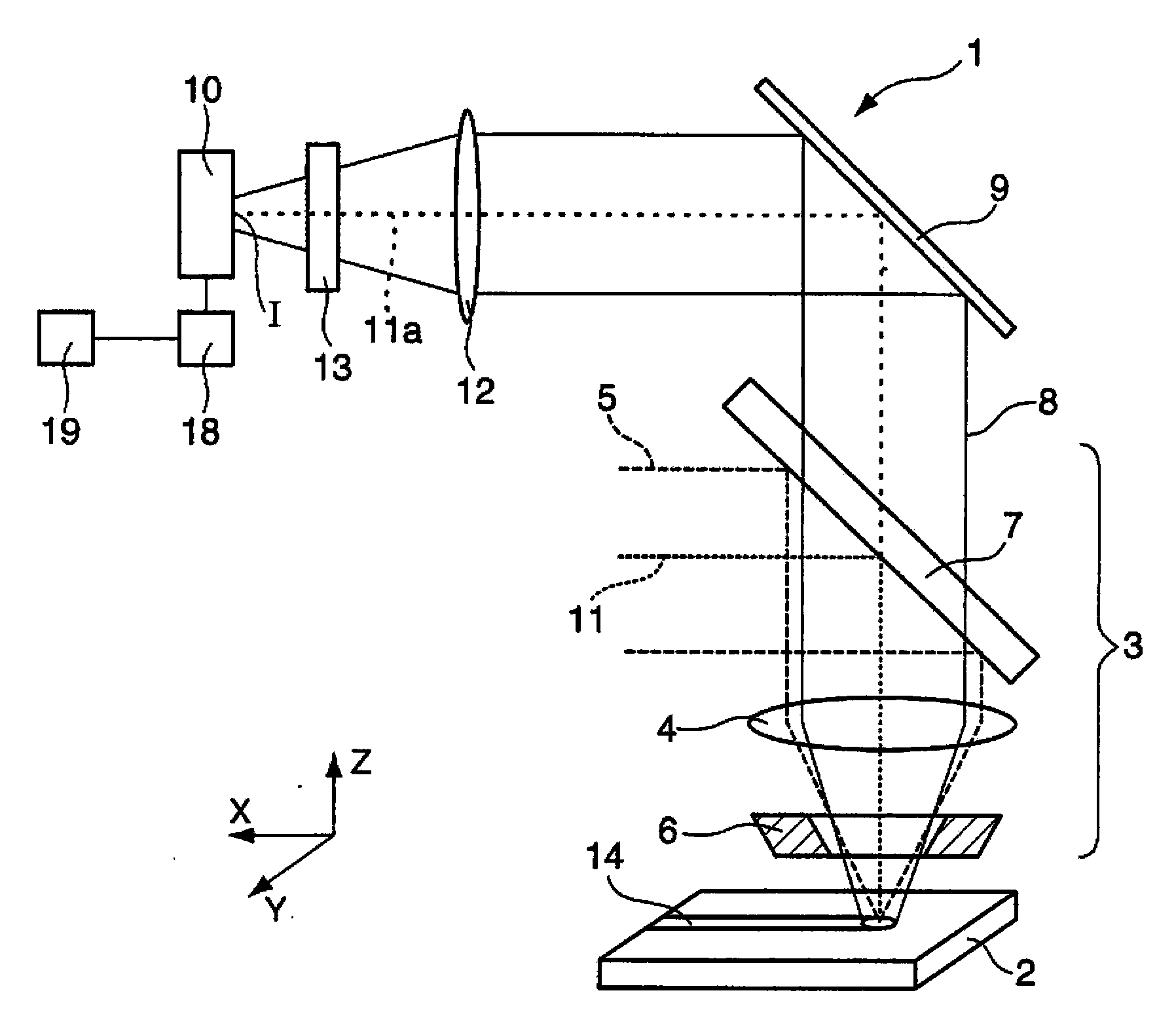
[0026] figure 1A detail of a laser processing machine 1 for cutting a workpiece 2 is shown, which includes a processing unit in the form of a laser processing head 3 . The laser processing head 3 has a focusing lens 4, which is made of zinc selenide and serves to divert CO 2 - laser beam 5 focused, the CO 2 - the laser beam is powered by (not shown) CO 2 -Laser generation. In the case of the present invention, the turning mirror 7 is configured to be partially transmissive and will convert the incident CO 2 - the laser beam 5 (with a wavelength of about 10 μm) reflects and transmits the radiation 8 from the workpiece 2 which is important for process monitoring, said radiation 8 being in the wavelength range, namely in the example of the invention between about 550 nm and 2000 nm between. It is understood that the laser processing machine 1 described here can also have a (not shown) solid-state laser beam source (such as a disk laser or a fiber laser), which has a radiatio...


PUM


Abstract

A method for monitoring cutting processing on a workpiece whereby a part of the workpiece is separated from a remainder of the workpiece along a desired cut contour, wherein, after the cutting processing, the following steps are carried out: irradiating the workpiece with a laser beam at a location within the desired cut contour, detecting radiation generated by an interaction between the laser beam and the workpiece, and evaluating the detected radiation to determine whether, during the cutting processing, the part of the workpiece was completely separated from the remainder of the workpiece. The invention also relates to a laser processing machine for carrying out the method.

Description

technical field [0001] The invention relates to a method for checking a cutting operation on a workpiece for separating parts of the workpiece from the remainder of the workpiece along a desired cutting contour. The invention also relates to a laser processing machine for performing cutting operations on a workpiece to separate parts of the workpiece from the remainder of the workpiece along a desired cutting profile. Background technique [0002] In particular, the cutting process of a plate-shaped workpiece (for example a sheet metal) can be carried out by means of thermal processing (for example by cutting with a laser beam) or by means of mechanical processing (for example by punching (nibbling)). During laser processing, the cutting is carried out by means of a laser processing head which is moved along a predetermined cutting hub relative to the workpiece arranged in the processing plane. In order to generate a relative movement, the laser processing head and / or the w...

Claims


Application Information

Patent Timeline
IPC IPC(8): B23K26/38B23K26/03
CPCB23K2203/04B23K26/38B23K26/032B23K26/422B26D5/007B23K26/702B23K2103/04Y10T83/04Y10T83/865
Inventor T·哈根洛赫M·齐默尔曼
Owner TRUMPF LASERSYST FOR SEMICON MFG
Why Eureka
Try Eureka