Positive end expiratory pressure valve pressure control device

A positive end-expiratory pressure, pressure control technology, applied in respirator and other directions, to achieve the effect of simple design, improved reliability, and shortened lag time

Active Publication Date: 2013-10-30
上海力申科学仪器有限公司
View PDF3 Cites 4 Cited by
  • Summary
  • Abstract
  • Description
  • Claims
  • Application Information

AI Technical Summary

Problems solved by technology

[0003] In order to solve the problems of rapid response, precise adjustment and stability of the pressure control of the PEEP valve, without increasing the cost of the ventilator, the present invention provides a structure for effectively controlling the pressure of the PEEP valve, which can be used to realize the ventilator and anesthesia machine positive end-expiratory pressure

Method used


Image

  • Positive end expiratory pressure valve pressure control device
  • Positive end expiratory pressure valve pressure control device
  • Positive end expiratory pressure valve pressure control device

Examples


Embodiment Construction

[0022] The pressure control device for the positive end-expiratory pressure valve of the present invention will be further described in detail below in conjunction with the accompanying drawings.

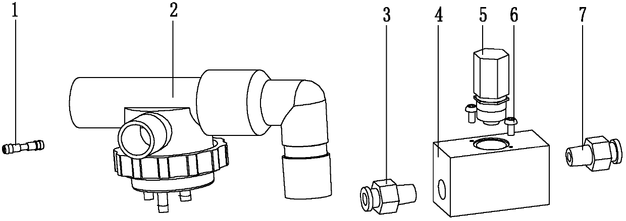
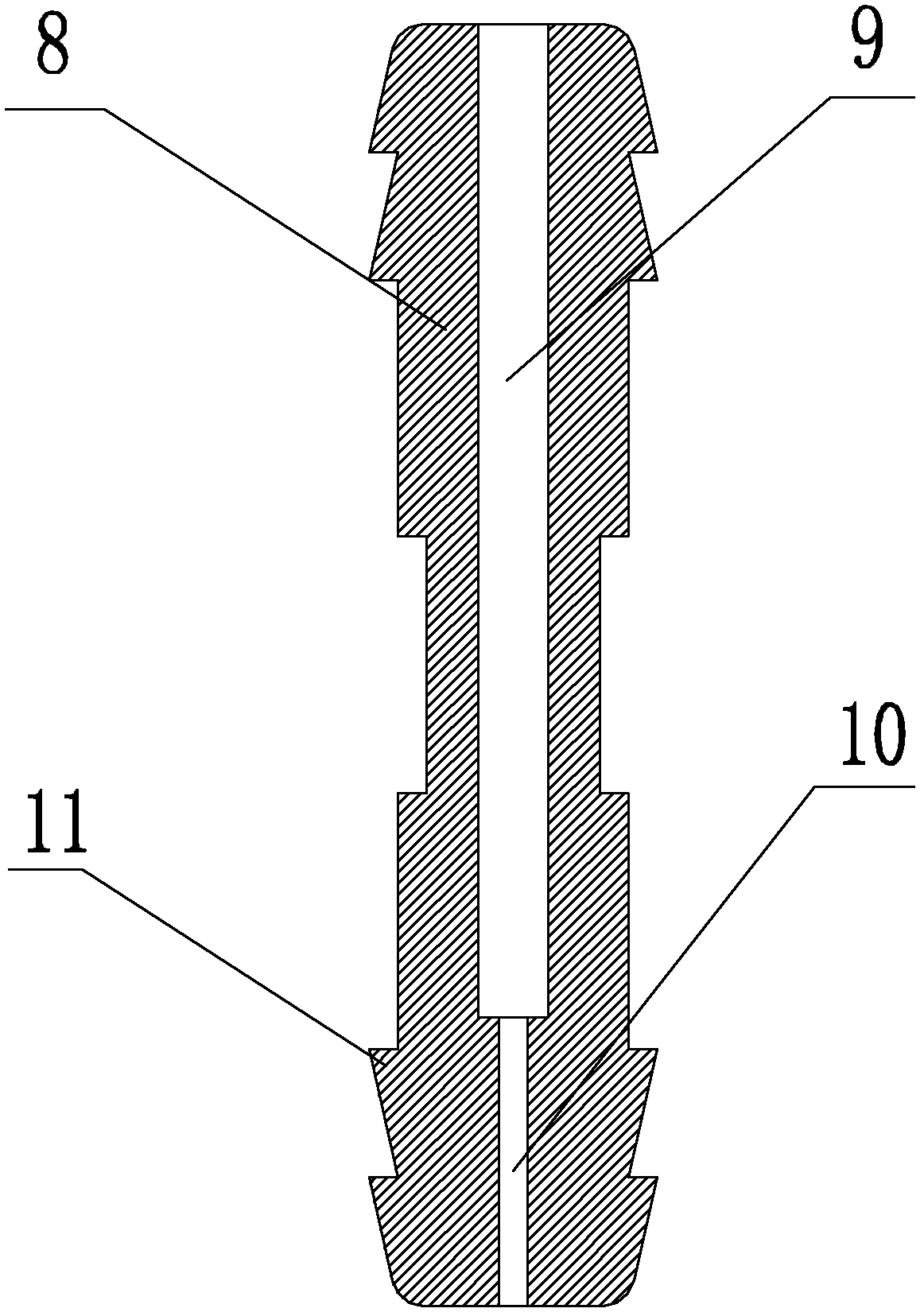
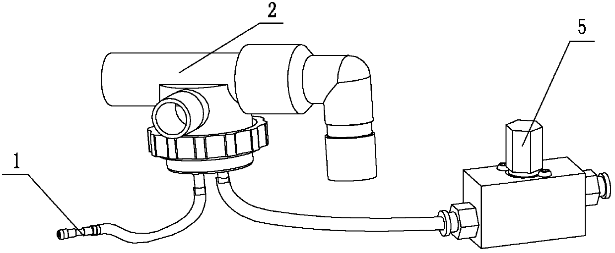
[0023] like figure 1 , figure 2 , image 3 , Figure 4 , Figure 5 As shown, the positive end-expiratory pressure valve pressure control device of the present invention includes: a flow-limiting capillary copper tube 1, an exhalation valve 2, and a proportional valve mounting seat 4 connected to each other in sequence, and the first quick-change joint 3 is fixedly connected to the proportional valve. On the seat 4, it is connected with the PEEP chamber of the exhalation valve 2 through a hose, and the periphery of the flow-limiting capillary copper tube 1 is a pagoda-shaped double-layer barb, which can be sealed and connected with the gas pipeline. The flow proportional valve 5 is installed on the proportional valve mounting seat 4 through two fixing screws 6 , and a second qui...


PUM


Abstract

The invention relates to a positive end expiratory pressure valve pressure control device which comprises an exhalation valve 2, a proportional valve installation base 4, a flow proportional valve 5 and a current-limiting capillary copper pipe 1, wherein one end of the proportional valve installation base 4 is connected with one end of the exhalation valve 2, the flow proportional valve 5 is arranged on the proportional valve installation base 4, and the current-limiting capillary copper pipe 1 is connected at the other end of the exhalation valve 2. The positive end expiratory pressure valve pressure control device is characterized in that the pressure control device is simple in design, only one current-limiting capillary copper pipe 1 is additionally arranged in the traditional structure, cost of the current-limiting capillary copper pipe 1 can be ignored, fixed low flow and pressure input are supplied in a positive end expiratory pressure (PEEP) cavity of the exhalation valve 2, and the flow proportional valve 5 is used for controlling the caliber of an exhaust port located in the PEEP cavity of the exhalation valve 2 so as to change the PEEP. Matching requirements on the flow proportional valve 5 and hardware platforms is correspondingly reduced, the exhaust end of the flow proportional valve 5 is directly connected with the air, fast response can be carried out along with valve adjustment, the delay time is shortened, and reliability of breathing machines is improved.

Description

technical field [0001] The invention relates to a very important safety component in a ventilator (the ventilator belongs to Class III equipment in medical equipment), in particular to positive end-expiratory pressure (PEEP) for ventilators and anesthesia machines valve control system. Background technique [0002] The ventilator and anesthesia machine use the PEEP valve to keep the airway at a certain positive pressure at the end of the exhalation, so that the alveoli will not completely shrink, and the collapsed alveoli can be expanded and the atelectatic alveoli can be recruited, thus increasing the functional residual capacity and The compliance of the lungs facilitates the diffusion of oxygen through the expiratory membrane. Therefore, PEEP can effectively accelerate the repair process by improving oxygenation, avoid damage to lung tissue, and win opportunities for comprehensive treatment. Therefore, having the PEEP function has become an important performance index of...

Claims


Application Information

Patent Timeline
IPC IPC(8): A61M16/20
Inventor 宋智广黄敏
Owner 上海力申科学仪器有限公司
Why Eureka
Try Eureka