Pneumatic tire

A technology of pneumatic tires and tires, which is applied to the reinforcement layer, tire parts, tire edges and other directions of pneumatic tires to achieve the effect of ensuring rigidity and reducing energy loss

Inactive Publication Date: 2013-10-30
SUMITOMO RUBBER IND LTD
View PDF5 Cites 8 Cited by
  • Summary
  • Abstract
  • Description
  • Claims
  • Application Information

AI Technical Summary

Problems solved by technology

[0006] However, in such pneumatic tires as described above, there is room for further improvement in the maintenance of steering stability and the reduction of rolling resistance.

Method used


Image

  • Pneumatic tire
  • Pneumatic tire
  • Pneumatic tire

Examples


Embodiment

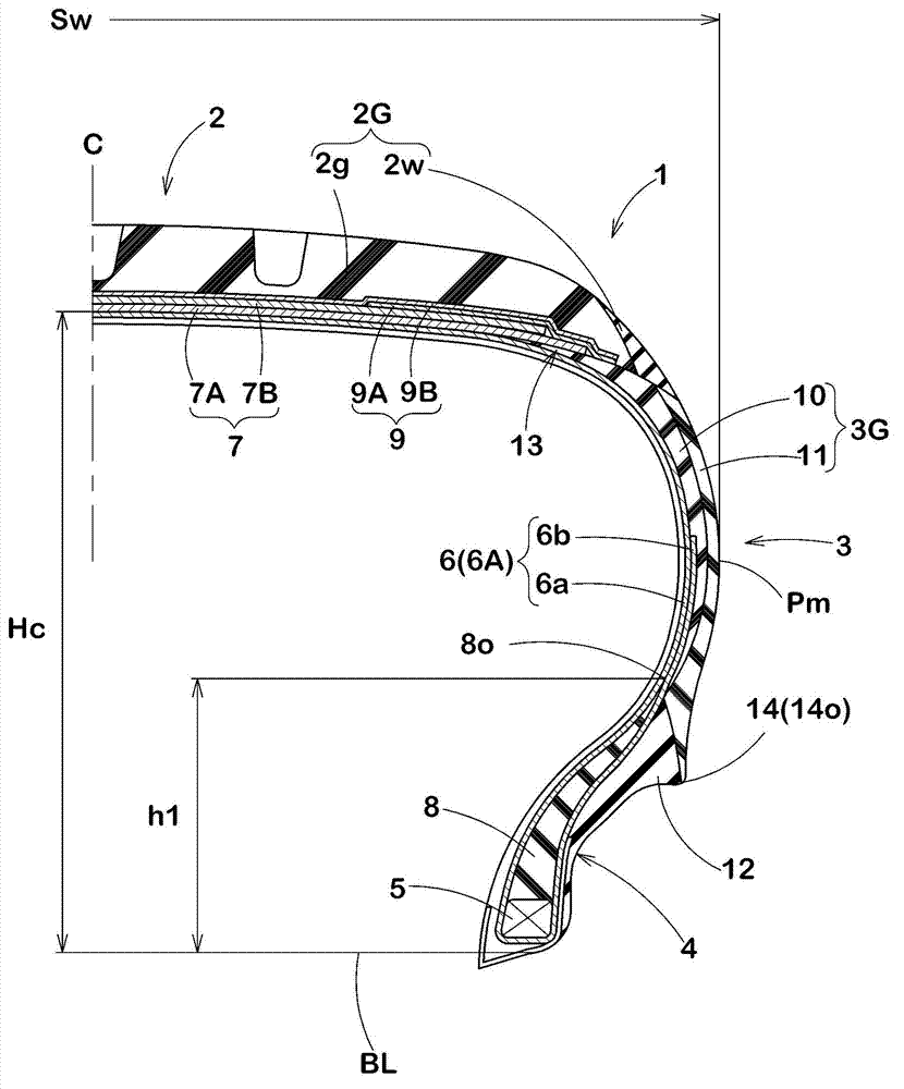
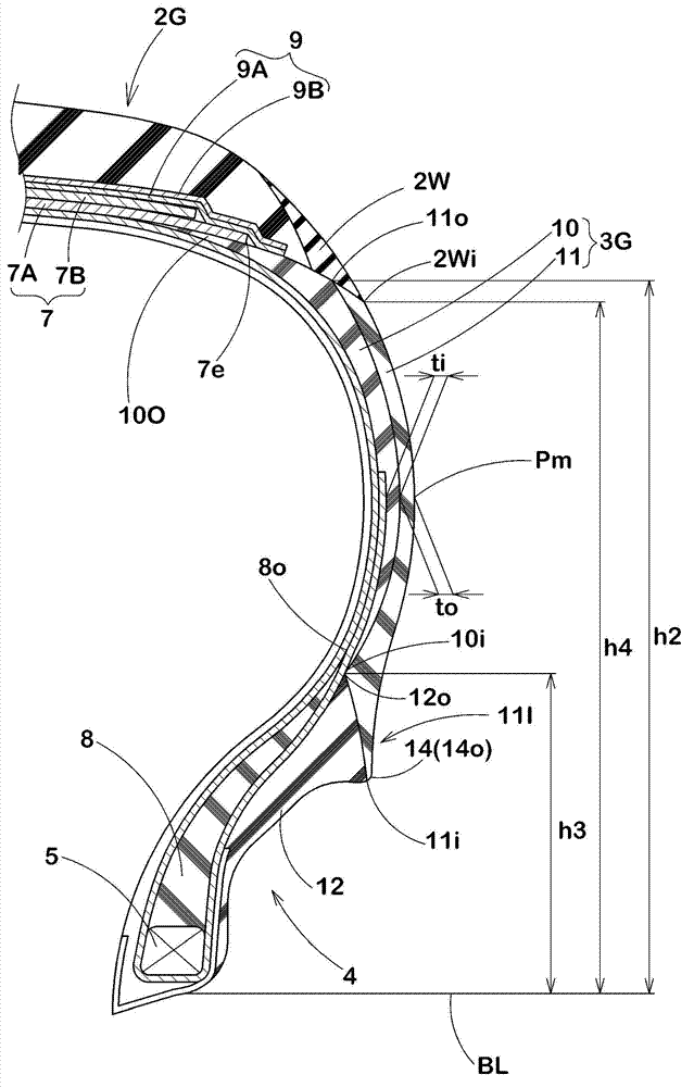
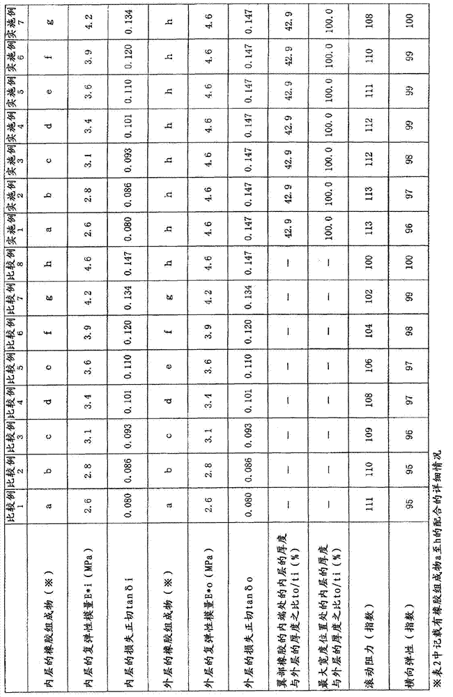
[0072] Based on the specifications in Table 1, a trial-manufactured form figure 1 The basic structure of 205 / 55R16 passenger car tires, and the lateral elasticity and rolling resistance of each test tire were tested. In addition, as a comparative example, the same test was performed on rubbers in which the outer layer and the inner layer were composed of the same rubber composition. The test method is as follows.

[0073]

[0074] The rolling resistance of the test tires was measured using a rolling resistance tester under the following conditions. The results are expressed by an index whose reciprocal of the rolling resistance of Comparative Example 8 is 100. The larger the numerical value, the smaller the rolling resistance.

[0075] Mounting rim: 16×6.5JJ

[0076] Internal pressure: 210kPa

[0077] Longitudinal load: 4.83kN

[0078]

[0079] The lateral elasticity of the test tires was measured using a static testing machine under the following conditions. The res...


PUM


Abstract

Pneumatic tire (1) with carcass (6) and sidewall rubbers (3G), wherein the sidewall rubber (3G) includes an inner layer (10) and an outer layer (11); the outer layer (11) has a complex elastic modulus E* higher than the inner layer (10) and a thickness that is (to) which is gradually increased from the maximum width position (Pm) towards the radially inner end; the inner layer (10) has a loss tangent tan ´ lower than that of the outer layer (11) and a thickness (ti) which is gradually reduced from the maximum width position (Pm) towards the radially inner end and gradually increased from this point to the radially outer end.

Description

technical field [0001] The present invention relates to a pneumatic tire that maintains steering stability and reduces rolling resistance. Background technique [0002] In recent years, in consideration of energy saving, it is required to reduce the rolling resistance of tires and to improve the fuel consumption performance of vehicles. Generally, about half of the rolling resistance of a tire is converted into energy loss due to heating of the rubber portion of the tire. Therefore, conventionally, a pneumatic tire has been proposed that reduces the rolling resistance of the tire by using a rubber material having a small energy loss due to heat for a sidewall portion having a large degree of deformation. [0003] However, in such a pneumatic tire, the durability of the sidewall portion may also be reduced in addition to the decrease in the steering stability due to the decrease in the rigidity of the sidewall portion. [0004] In response to such a problem, Patent Document...

Claims


Application Information

Patent Timeline
Patent Type & Authority Applications(China)
IPC IPC(8): B60C13/00
CPCB60C13/04B60C2013/007B60C2013/006B60C2013/045Y02T10/86B60C9/18B60C15/06
Inventor 辰巳宽之
Owner SUMITOMO RUBBER IND LTD
Why Eureka
Try Eureka