Control device of vehicle driving apparatus

A vehicle driving device and control device technology, which is applied in the direction of engine-driven traction, vehicle energy storage, vehicle components, etc., can solve the problems of vehicle driver discomfort, etc., and achieve good vehicle drivability, less discomfort, The effect of maintaining the drivability of the vehicle

Active Publication Date: 2013-10-30
HONDA MOTOR CO LTD
View PDF8 Cites 2 Cited by
  • Summary
  • Abstract
  • Description
  • Claims
  • Application Information

AI Technical Summary

Problems solved by technology

Therefore, causing a temporary decrease in the driving force o

Method used


Image

  • Control device of vehicle driving apparatus
  • Control device of vehicle driving apparatus
  • Control device of vehicle driving apparatus

Examples


no. 1 Embodiment approach

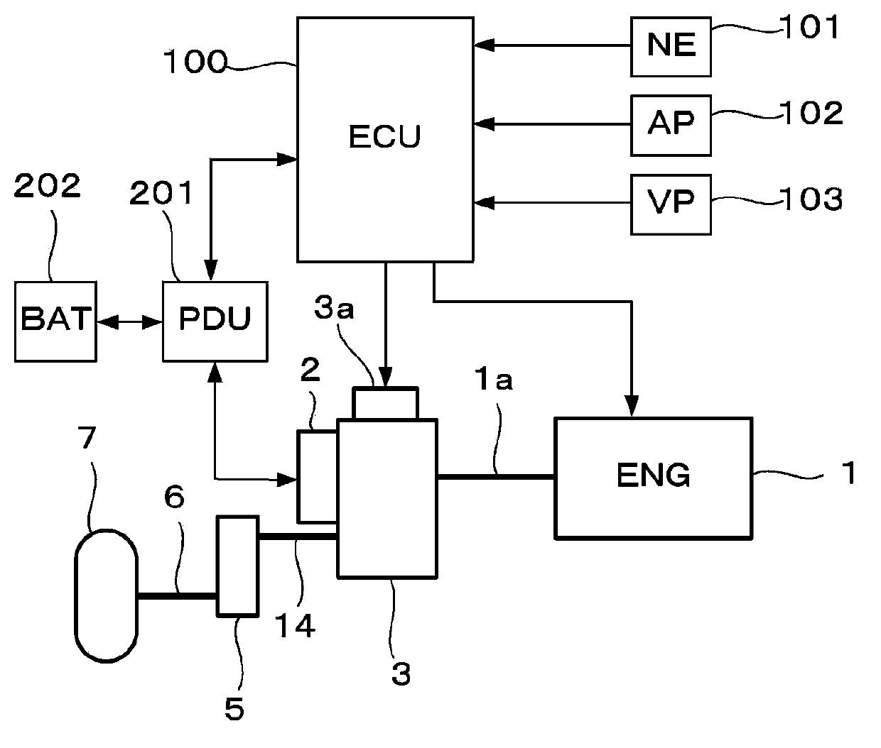
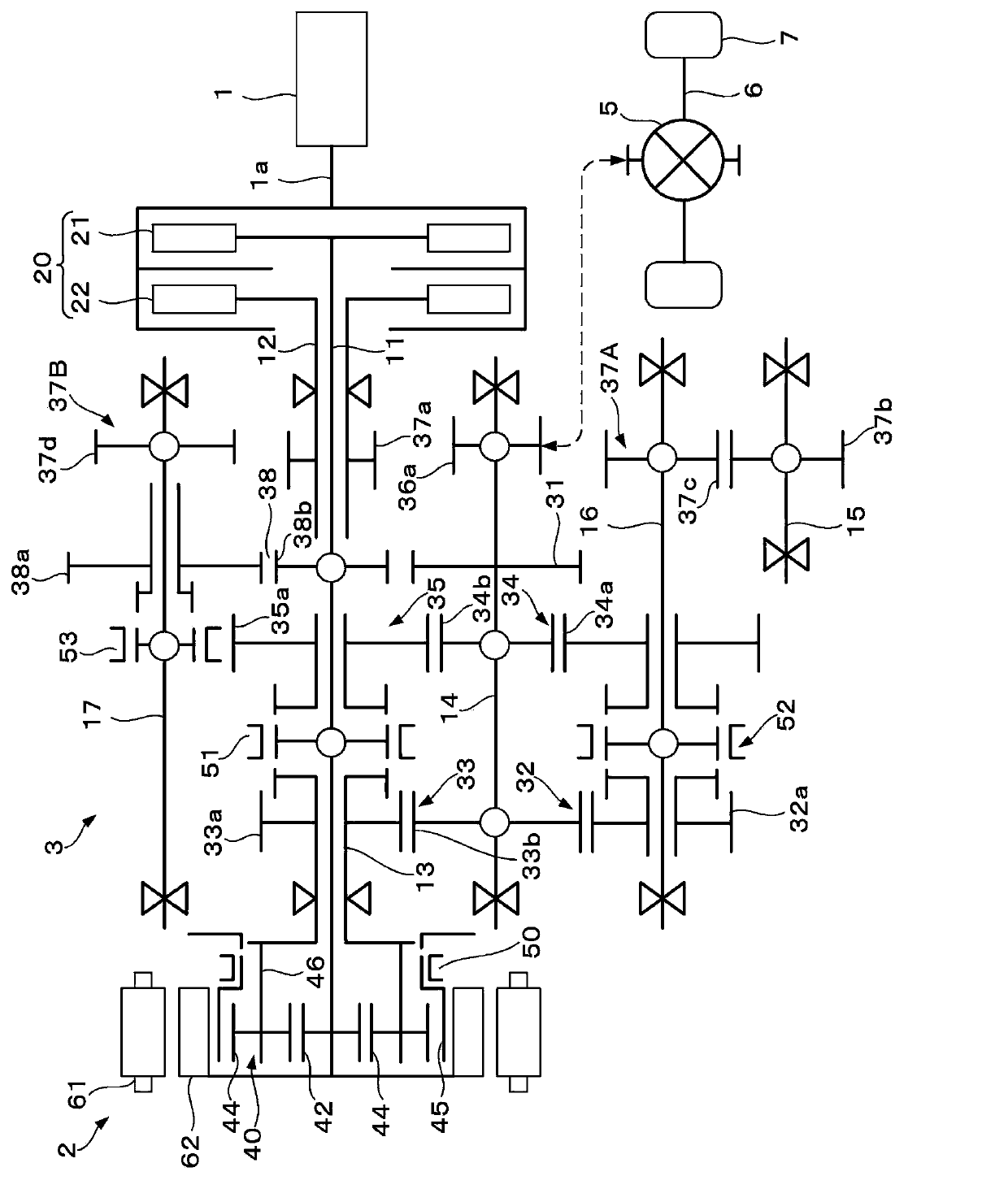
[0032] figure 1is a diagram showing the overall configuration of a vehicle drive device and its control device according to an embodiment of the present invention, figure 2 yes figure 1 Skeleton diagram of the vehicle drive unit shown. The vehicle driving device shown in these figures has: an internal combustion engine (hereinafter referred to as "engine") 1 as a prime mover, an electric motor (hereinafter referred to as "motor") that functions as a prime mover and a generator (hereinafter referred to as "motor") 2, an engine for transmitting 1 and / or the transmission 3 of the driving force of the motor 2 is configured to drive the drive wheels 7 via the countershaft 14 , the differential gear mechanism 5 , and the drive shaft 6 as the output shaft of the transmission 3 . The motor 2 is connected to a power drive unit (hereinafter referred to as “PDU”) 201 , and the PDU 201 is connected to a battery 202 .

[0033] When the motor 2 is driven with a positive drive torque, ...

no. 2 Embodiment approach

[0117] This embodiment is further added to the first embodiment Figure 9 The variable speed control process shown. Figure 9 The shown processing is included in the shift control processing executed by the ECU 100 , upshifting or downshifting corresponding to the change amount DAP of the accelerator pedal operation amount AP is performed, and is executed every predetermined time TCAL.

[0118] In step S31 , a change amount (hereinafter referred to as “AP change amount”) DAP of the accelerator pedal operation amount is calculated by the following equation (1).

[0119] DAP=AP-APZ (1)

[0120] Here, "AP" and "APZ" are the current value and the previous value (the value before the predetermined time TCAL) of the accelerator pedal operation amount.

[0121] In step S32, it is determined whether the upshift possible flag FUPSHP is "1", and if the answer is affirmative (Yes), it is determined whether the injection request flag FRFLR is "1" (step S33). The injection request flag ...


PUM


Abstract

The invention provides a control device of a vehicle driving apparatus, allowing a clutch to carry out injection action on an oil pressure actuator for driving and suppressing discomfort caused to driver. The vehicle driving apparatus comprises a generator (1) and a motor (2), wherein the generator (1) drives the vehicle through a clutch, and the motor (2) is configured to drive the vehicle without the clutch. Following injection action is carried out when the injection action request is sent. When a vehicle can be driven through the motor (2), the vehicle driving torque is compensate based on the motor (2) and the clutch in a joint state is broken off, and an enclosed oil pressure loop (80) corresponding to the breaking clutch communicates with a work oil storage tank (74). Since the vehicle driving torque is compensate through the motor (2) when the clutch is broken off, the lowering of vehicle driving torque due to injection action can be prevented, thereby maintaining excellent vehicle driving performance.

Description

technical field [0001] The present invention relates to a control device for a vehicle drive device, and more particularly to a control device for a vehicle drive device including a transmission having two clutches respectively corresponding to odd-numbered gears and even-numbered gears of a transmission mechanism. Background technique [0002] Patent Document 1 discloses a vehicle drive device including a transmission having two clutches respectively corresponding to odd-numbered shift speeds and even-numbered shift speeds of the transmission mechanism, as a hydraulic actuation for engaging / disengaging the clutches. As an actuator, a hydraulic actuator disclosed in Patent Document 2 is known. [0003] Such as Figure 10 As shown, the hydraulic actuator disclosed in Patent Document 2 has: a driven-side piston PR for moving a clutch disc, a driving-side piston PD that generates hydraulic pressure to drive the driven-side piston PR, and a connecting drive-side piston PR. Pist...

Claims


Application Information

Patent Timeline
IPC IPC(8): B60W10/02B60W10/08B60W10/105B60W30/18B60L50/16
CPCY02T10/7077Y02T10/6221Y02T10/62Y02T10/7072
Inventor 大久保慎一
Owner HONDA MOTOR CO LTD
Why Eureka
Try Eureka