
A mask table for exposure device

A technology of exposure device and mask stage, applied in the field of mask stage, can solve problems such as difficult application and large object distance of objective lens, etc., and achieve the effects of solving compatibility problems, improving use scalability, and reducing the complexity of structural design

Active Publication Date: 2015-08-26
SHANGHAI MICRO ELECTRONICS EQUIP (GRP) CO LTD
View PDF8 Cites 0 Cited by
  • Summary
  • Abstract
  • Description
  • Claims
  • Application Information

AI Technical Summary

Problems solved by technology

However, since the micro-motion stage is arranged on the coarse motion stage, the requirements for the distance between the objective lens and the object lens are very large, so it is difficult to apply to the field of splicing lens flat panel display lithography machine

Method used


Image

  • A mask table for exposure device
  • A mask table for exposure device
  • A mask table for exposure device

Examples


Embodiment Construction

[0036] In order to make the above objects, features and advantages of the present invention more comprehensible, specific implementations of the present invention will be described in detail below in conjunction with the accompanying drawings.

[0037] The invention provides a mask stage of a splicing lens exposure device with a large field of view, which has the functions of horizontal precision fine-tuning and large-stroke scanning movement, and has the functions of mechanical pre-alignment and compatibility with large and small reticles.

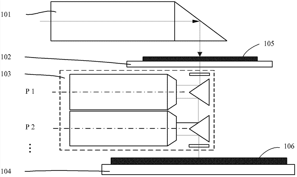
[0038] figure 1 It is a structural schematic diagram of the splicing exposure device. It can be seen from the figure that the splicing lens exposure device mainly includes an illumination system 101 , a mask stage 102 , a projection objective lens 103 , and a substrate stage 104 . The illumination system 101 is located above the mask table 102 and provides exposure light source for the exposure device. The mask table 102 supports and posi...


PUM


Abstract

The invention discloses a mask stage for an exposure device. The mask stage comprises a mechanical pre-alignment table and a driving mechanism, wherein the mechanical pre-alignment table comprises a bearing table, an X-direction pre-alignment mechanism and a Y-direction pre-alignment mechanism; the bearing table is used for fixing at least two masks of different sizes; the X-direction pre-alignment mechanism is used for realizing X-direction pre-alignment of the masks of different sizes; the Y-direction pre-alignment mechanism is used for realizing Y-direction pre-alignment of the masks of different sizes; the driving mechanism comprises a Y-direction coarse motion motor and an X-direction micro motion motor; the Y-direction coarse motion motor drives the mechanical pre-alignment table to perform scanning movement along the direction Y so as to perform large-travel scanning; the X-direction micro motion motor drives the mechanical pre-alignment table to move along the direction X so as to realize fine adjustment of the X / Rz direction. The driving mechanism has a single-layer driving structure, the structural design complexity of the mask stage in a small-object distance exposure device is reduced, and a compatible function of large and small masks is realized through the mechanical pre-alignment table; moreover, according to the driving mechanism, a traditional mechanical guide structure is omitted, and the mask stage structure is effectively simplified.

Description

technical field [0001] The invention relates to a mask table, in particular to a mask table used in a large field of view exposure device. Background technique [0002] The photolithography apparatus in the prior art is mainly used in the manufacture of integrated circuits (ICs) or flat panel displays and other micro devices. With a photolithographic apparatus, multilayer masks with different mask patterns are sequentially imaged in precise alignment on a photoresist-coated wafer, such as a semiconductor wafer or an LCD panel. Lithography devices are generally divided into two categories, one is a stepping lithography device, the mask pattern is exposed and imaged on one exposure area of ​​the wafer, and then the wafer moves relative to the mask to move the next exposure area to the mask pattern and under the projection objective, the mask pattern is again exposed on another exposed area of ​​the wafer, and the process is repeated until all exposed areas on the wafer have a...

Claims


Application Information

Patent Timeline
Patent Type & Authority Patents(China)
IPC IPC(8): G03F7/20G03F9/00
Inventor 江旭初
Owner SHANGHAI MICRO ELECTRONICS EQUIP (GRP) CO LTD
Learn More