Method and system for testing low-voltage differential signals

A low-voltage differential signal and test system technology, applied in electronic circuit testing, semiconductor/solid-state device testing/measurement, electrical measurement, etc., can solve problems such as error-prone, unable to meet the competitive needs of fast and high-quality production, and low efficiency. Achieve the effect of meeting competitive demands, eliminating test result errors, and shortening test time

Inactive Publication Date: 2013-10-30
NVIDIA CORP
View PDF6 Cites 6 Cited by
  • Summary
  • Abstract
  • Description
  • Claims
  • Application Information

AI Technical Summary

Problems solved by technology

[0004] At present, the test of low-voltage differential signals mainly relies on the manual operation of the operator. The manual test method is not only inefficient, but also prone to errors, which cannot meet the competitive needs of fast and high-quality production.

Method used


Image

  • Method and system for testing low-voltage differential signals
  • Method and system for testing low-voltage differential signals
  • Method and system for testing low-voltage differential signals

Examples


Embodiment Construction

[0033] In this application, exemplary embodiments will be described around a real-time error correction system and a navigation device using the system. Those of ordinary skill in the art should realize that the following description is only exemplary and not intended to be limiting in any way. Inspiration for other embodiments will readily occur to those skilled in the art having the benefit of this application. Now, implementation of the exemplary embodiments as shown in the accompanying drawings will be described in more detail. Wherever possible, the same reference numbers will be used throughout the drawings and the following description to refer to the same or like items.

[0034] Reference will now be made in detail to the preferred embodiments of the invention, examples of which are illustrated in the accompanying drawings.

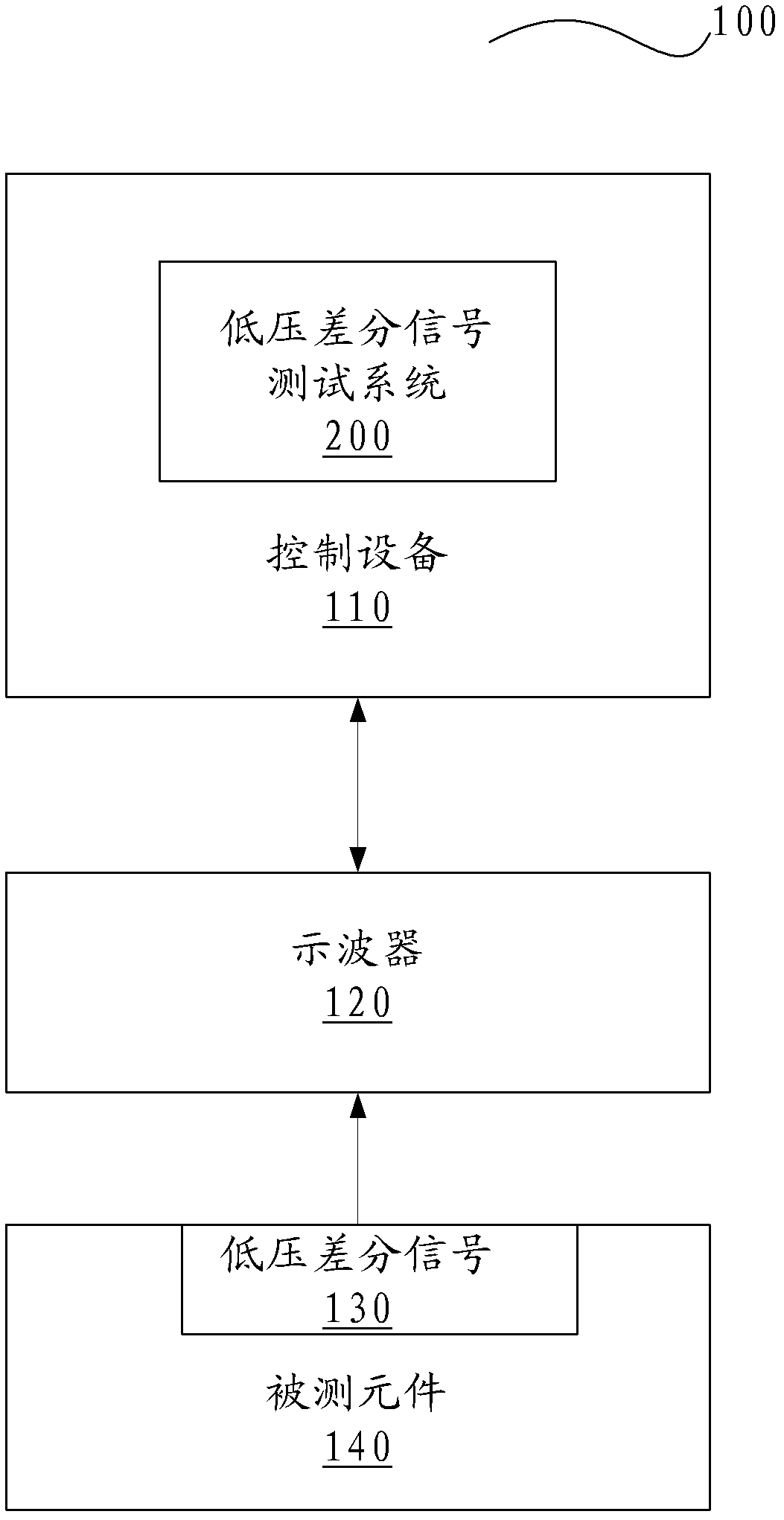
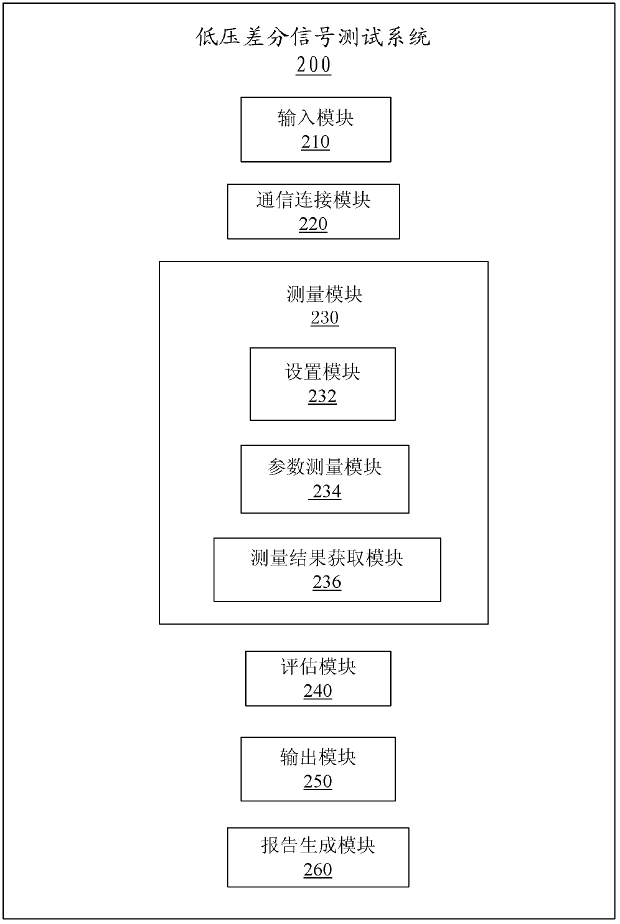
[0035] One aspect of the present invention provides a low-voltage differential signal test system 200. The signal test system can efficiently t...


PUM


Abstract

A test system and method for low voltage differential signaling (LVDS) is provided. The system comprises: an input module for the user to input the information needed by the test; a communication module for connecting the control device 110 and the oscilloscope 120 using the communication means selected by the user; a measurement module for measure the parameters of the LVDS signal thought controlling a oscilloscope; an assessment module for assessing whether the obtained parameters of the LVDS signal comply with relevant LVDS specifications; and an output module for outputting the parameters of the LVDS signal and the assessment result of the parameters from the assessment module. The test system and method for LVDS provided by the present invention can advantageously meet the competitive needs in fast mass production and efficient engineering qualification.

Description

technical field [0001] The present invention relates to a signal testing system and method, in particular to a low-voltage differential signal testing system and method. Background technique [0002] In the manufacture of semiconductor devices, it often happens that various parameters of electrical signals need to be tested to verify that they are working properly. Information obtained through testing can be used to flag and reject devices that do not perform as expected. Test results can sometimes be used to change steps in the device manufacturing process. For example, the device can be corrected in subsequent steps to match expected performance. [0003] As the performance of semiconductor devices improves, the difficulty of testing semiconductor devices also increases. The working speed of electronic systems has become faster and faster, and the use of Low Voltage Differential Signal (LVDS) in fast signals has become more and more common. Low Voltage Differential Sign...

Claims


Application Information

Patent Timeline
Patent Type & Authority Applications(China)
IPC IPC(8): H01L21/66G01R19/04G01R29/00
CPCG01R31/28G01R29/00G01R19/04G01R31/2851
Inventor 韩晓东周毅胡涛布伦登·召
Owner NVIDIA CORP
Why Eureka
Try Eureka