
Transmission method and device for DRS

A transmission method and a technology for transmitting subframes, which are applied in the field of DRS transmission methods and devices, can solve problems such as low downlink transmission efficiency and cannot be used for DRS transmission, and achieve the effect of improving downlink transmission efficiency

Active Publication Date: 2013-10-30
DATANG MOBILE COMM EQUIP CO LTD
View PDF4 Cites 8 Cited by
  • Summary
  • Abstract
  • Description
  • Claims
  • Application Information

AI Technical Summary

Problems solved by technology

[0029] The purpose of the present invention is to provide a DRS transmission method and device to solve the problem of low downlink transmission efficiency caused by the fact that the RB where the subcarrier carrying the synchronization signal in the NCT carrier is located cannot be used to transmit the DRS

Method used


Image

  • Transmission method and device for DRS
  • Transmission method and device for DRS
  • Transmission method and device for DRS

Examples


Embodiment Construction

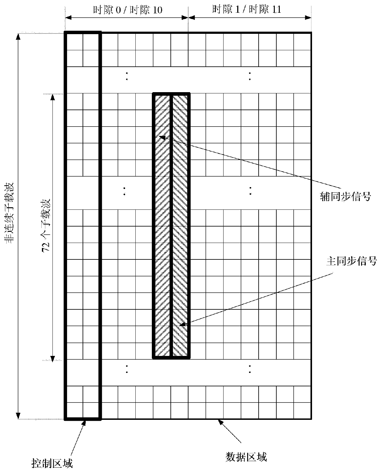
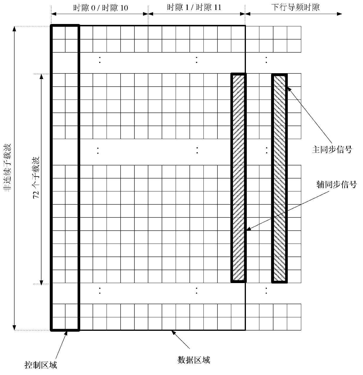
[0077] Based on the asynchronous NCT carrier specified in LTE Rel11, the present invention provides a resource mapping method for DRS on the antenna port where it is transmitted. The main idea is: DRS is mapped on REs other than the REs occupied by synchronization signals, In order to support simultaneous transmission of the DRS and the synchronization signal in the same downlink subframe. In the embodiment of the present invention, the synchronization signal refers to PSS / SSS.

[0078] On the eNB side, a DRS transmission method provided by an embodiment of the present invention is as follows: Figure 4 As shown, it specifically includes the following operations:

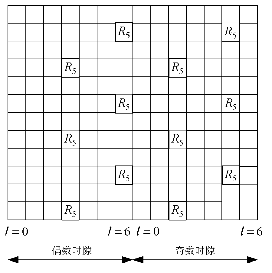
[0079] Step 100: Map the DRS that needs to be transmitted on the antenna port p to the RE used for transmitting the DRS in the downlink subframe according to the resource mapping method of the DRS on the antenna port p; The number of the OFDM symbol where the RE used to transmit the DRS is different from the numbe...


PUM


Abstract

The invention discloses a transmission method and device for a DRS. The method comprises the steps that according to a resource mapping mode, of the DRS, in an antenna port p, the DRS needing to be transmitted on the antenna port p is mapped to an RE, used for transmitting the DRS, in a downlink sub-frame, in the same time slot position, the serial number of an OFDM sign where the RE, used for transmitting the DRS, in the downlink sub-frame belongs to is different from the serial number of the OFDM sign where an RE, used for transmitting a synchronous signal, in a synchronous signal transmission sub-frame, and the antenna port p is used for transmitting the downlink sub-frame. As mapping resources of the DRS in the downlink sub-frame and the synchronous signal are not overlapped, for asynchronous NCT carrier waves, the DRS and downlink data can be simultaneously transmitted in the synchronous signal transmission sub-frame, and the downlink transmission efficiency of the asynchronous NCT carrier waves is improved. As the DRS can be transmitted in the synchronous signal transmission sub-frame, the downlink data can be received normally.

Description

technical field [0001] The present invention relates to the field of communication technologies, in particular to a DRS transmission method and device. Background technique [0002] Introduction to LTE-ACA: [0003] In the LTE-A (Long Term Evolution-Advanced, Long Term Evolution Enhanced) system, the peak rate of the system is greatly improved compared with the LTE (Long Term Evolution, Long Term Evolution) system, and it is required to reach 1Gbps downlink and 500Mbps uplink. If only one carrier with a maximum bandwidth of 20MHz is used, the peak rate requirement cannot be met. Therefore, the LTE-A system needs to expand the bandwidth that UE (User Equipment, user equipment, also known as terminal) can use, thus introducing CA (Carrier Aggregation, carrier aggregation) technology, that is, multiple Contiguous or non-contiguous carriers are aggregated together to serve UEs simultaneously to provide the required rate. These aggregated carriers are also called a CC (Compone...

Claims


Application Information

Patent Timeline
Patent Type & Authority Applications(China)
IPC IPC(8): H04L5/00H04L27/26
CPCH04L5/0016H04L27/26H04L5/00H04L5/0023H04L5/0051
Inventor 高雪娟林亚男沈祖康
Owner DATANG MOBILE COMM EQUIP CO LTD
Learn More