Image encoding device and method and image decoding device and method

An image encoding and image decoding technology, which is applied in the field of image decoding devices, can solve the problems of increased device size and uncontrolled upper limit of the amount of encoding, and achieve the effects of suppressing accumulation, reducing the amount of encoding, and suppressing the upper limit of the amount of encoding

Active Publication Date: 2018-09-28
FUJIFILM BUSINESS INNOVATION CORP
View PDF11 Cites 0 Cited by
  • Summary
  • Abstract
  • Description
  • Claims
  • Application Information

AI Technical Summary

Problems solved by technology

[0007] In the JPEG system, the upper limit of the encoding amount is not controlled, and when processing multiple lines (for example, eight lines) of an image at the same time, the size of the device increases

Method used


Image

  • Image encoding device and method and image decoding device and method
  • Image encoding device and method and image decoding device and method
  • Image encoding device and method and image decoding device and method

Examples


Embodiment approach

[0043]

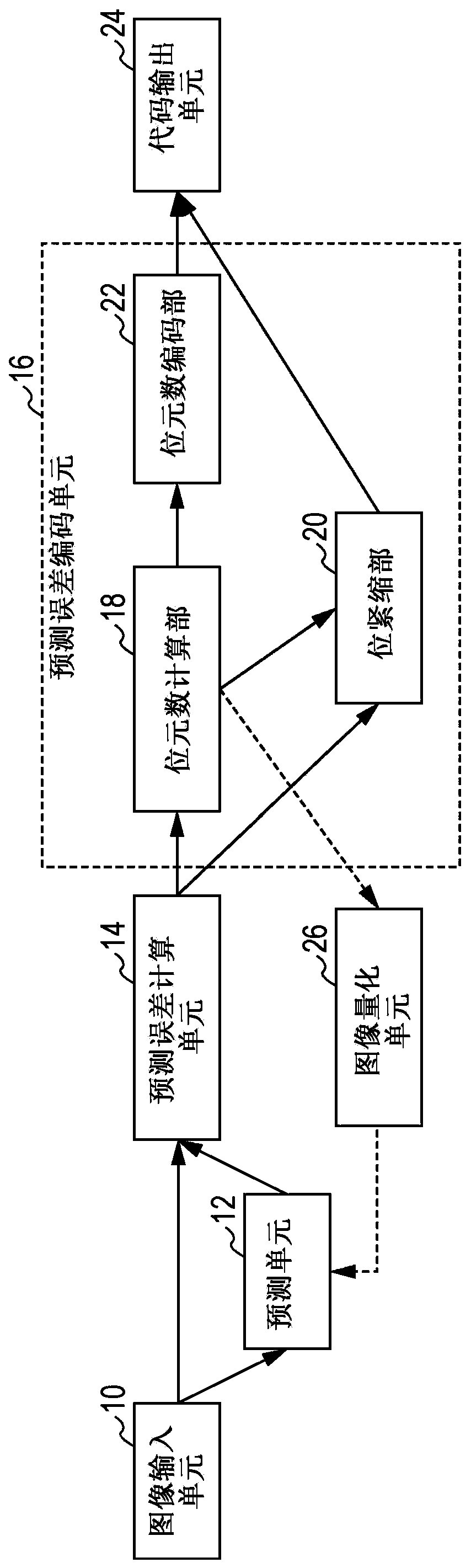
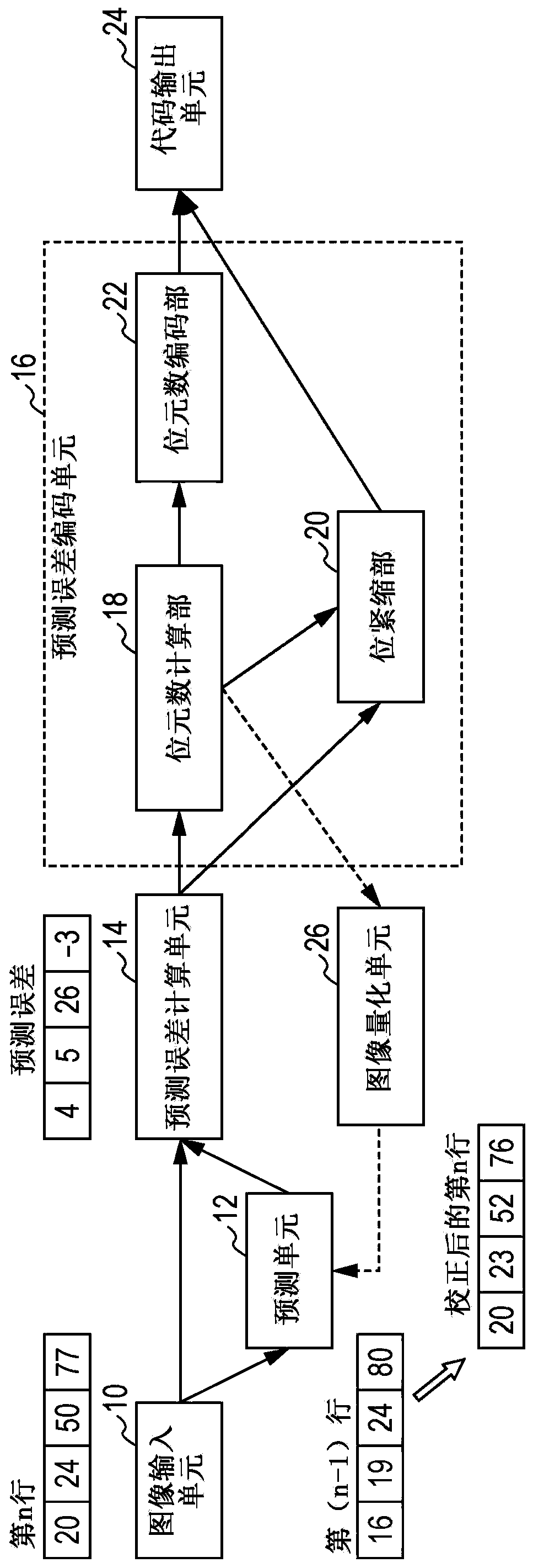
[0044] figure 1 is a functional block diagram of the image encoding device according to the first exemplary embodiment. The image encoding device includes an image input unit 10 , a prediction unit 12 , a prediction error calculation unit 14 , a prediction error encoding unit 16 , a code output unit 24 , and an image quantization unit 26 .

[0045] The image input unit 10 obtains image data as a processing object. Examples of the image input unit 10 include a scanner that scans a document and converts the document into electronic data. The image input unit 10 outputs the obtained image data to the prediction unit 12 and the prediction error calculation unit 14 .

[0046] The prediction unit 12 predicts a pixel value of a pixel of interest (ie, a pixel to be processed). For example, when performing line-by-line processing, the prediction unit 12 uses the pixel value of the line preceding the line of interest as a prediction value. More specifically, a horizontal ...


PUM


Abstract

The present invention provides an image encoding device and method, and an image decoding device and method. An image encoding device includes an input unit, a prediction unit, a prediction error calculation unit, and an encoder. The input unit receives image data as input. The prediction unit calculates a predicted pixel value of a pixel of interest serving as a processing object in the image data. The prediction error calculation unit calculates a prediction error value by using the actual pixel value and the predicted pixel value of the pixel of interest. The encoder encodes the prediction error value with information including the number of bits and the error value. When the number of bits exceeds the number of valid bits, the encoder encodes only one or more upper bits corresponding to the number of valid bits as an error value.

Description

technical field [0001] The present invention relates to an image encoding device and method and also relates to an image decoding device and method. Background technique [0002] So far, various systems for encoding or compressing images have been proposed. Such systems include Joint Photographic Experts Group (JPEG) and Block Truncation Coding (BTC). The former is a variable length encoding system that reduces the amount of encoding while keeping image quality degradation at a low level by combining frequency conversion and quantization. The latter is a fixed-length encoding system capable of encoding an image to a certain fixed encoding amount by expressing a block with information of a fixed length. [0003] Japanese Unexamined Patent Application Publication No. 63-76684 discloses an adaptive differential encoding system that, in setting the differential quantization characteristics of each color coordinate data representing a color image, with respect to color coordina...

Claims


Application Information

Patent Timeline
Patent Type & Authority Patents(China)
IPC IPC(8): H04N19/60H04N19/593H04N19/98
CPCH04N19/60H04N19/593H04N19/98G06T9/004
Inventor 横濑太郎
Owner FUJIFILM BUSINESS INNOVATION CORP
Why Eureka
Try Eureka