Material grinder

A pulverizer and material technology, applied in the direction of grain processing, etc., can solve the problems of lack of separation mechanism for coarse and fine materials, difficulty in fully pulverizing materials, and increased workload of personnel, so as to reduce workload, more fully pulverize, and improve pulverization efficiency. high effect

Inactive Publication Date: 2013-11-06
方城县三利热能开发有限公司
View PDF11 Cites 11 Cited by
  • Summary
  • Abstract
  • Description
  • Claims
  • Application Information

AI Technical Summary

Problems solved by technology

[0004] Its shortcomings are: 1) Lack of coarse and fine material separation mechanism, when returning and crushing materials that are difficult to crush at one time, repeated crushing of qualified materials will increase the burden on equipment, increase the workload of personnel, affect work efficiency and consume electricity Increase; 2) Cylindrical barrel structure, it is easy to cause the material to drop too fast, and it is difficult to fully crush the material

Method used


Image

  • Material grinder
  • Material grinder

Examples


Embodiment 1

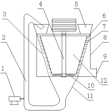
[0018] Such as figure 1 Shown: a material pulverizer, including a casing 8, an inverted frustum-shaped rotating body 12 and an inverted frustum-shaped filter support 3 are arranged in the casing 8, and the rotating body 12 is flexibly connected with the casing 8 through a main shaft 4 A fixed blade 6 and a movable blade 7 are arranged on its peripheral side, the filter support 3 is fixedly connected to the casing 8, and a funnel-shaped slag drop communicating with the filter support 3 is provided at the bottom of the casing 8. Hopper 11, the top of the casing is provided with a material feed port 5 and a slag feed port respectively, the slag drop hopper 11 communicates with the slag feed port through the return pipe 2, and the lower part of the side wall of the casing 8 Finished product discharge port 9 is set. The lower part of the main shaft 4 protrudes out of the rotating body 12 , and the protruding part is provided with a rotating blade 10 . The fixed blade 6 is horizon...

Embodiment 2

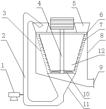
[0020] Such as figure 2 As shown: the difference between this embodiment and the first embodiment is that: the bottom of the casing 8 is a slope structure, the finished product discharge port 9 is set on one side of the bottom of the slope, the lower end of the main shaft 4 is provided with a bearing, and It is connected with the casing 8 through a support rod, and there are multiple finished product outlets 9 .

[0021] In the material pulverizer of the present invention, the material is sent into the pulverizer through the material feeding port, the material is cut and pulverized by the fixed blade and the movable blade on the rotating body, and the finished pulverized material that meets the requirements is filtered to the filter support through the filter support. In the cavity formed by the filter support and the casing, the slag whose crushing degree does not meet the requirements will continue to be crushed along the slope-shaped gap between the filter support and the ...


PUM


Abstract

The invention discloses a material grinder which comprises a machine casing, wherein a reversed frustum-shaped rotating body and a reversed frustum-shaped filtering support member are arranged in the machine casing, the rotating body is movably connected with the machine casing through a spindle, fixed blades and movable blades are distributed on the circumferential side of the rotating body, satisfactory smashed materials are filtered into a cavity formed by the filtering support member and the machine casing, satisfactory smashed materials and unsatisfactory slag cannot be fed back together, unnecessary work load of devices and staff can be reduced, device resistance is reduced, device efficiency is improved, a whole material down channel is in a gradually narrowed state, the materials performed with certain smashing procedures can still keep certain compactness when moving to a lower gap and the lower materials can be efficiently and fully smashed.

Description

technical field [0001] The invention relates to the technical field of material crushing equipment, in particular to a material crushing machine. Background technique [0002] At present, most of the traditional pulverizers on the market are horizontal pulverizers and lack the mechanism for separating coarse and fine materials. All materials are repeatedly crushed, which increases the workload of personnel and equipment, which is labor-intensive, time-consuming, inefficient, and high in power consumption; especially for some materials with high water content or bouncy materials, the situation is more serious, and often used in practical applications. If the screen is blocked or the machine is choked, the material is difficult to crush, and it is easy to cause the equipment to stop or even damage the equipment; this kind of material cannot be crushed with a jaw crusher or a wheel mill, and the material will be crushed. In the shape of a mud cake, the use of a hammer mill is ...

Claims


Application Information

Patent Timeline
Patent Type & Authority Applications(China)
IPC IPC(8): B02C18/08B02C18/18B02C18/22B02C23/12
CPCB02C18/10B02C18/18B02C23/32
Inventor 李伟东沈阳
Owner 方城县三利热能开发有限公司
Why Eureka
Try Eureka