Pin shaft machine

A shaft pin machine and shaft pin technology, applied in other manufacturing equipment/tools, manufacturing tools, etc., can solve the problems of unreasonable design, low degree of automation, waste of raw materials, etc., to save production materials, high degree of automation, and convenient maintenance. Effect

Active Publication Date: 2013-11-06
ZHEJIANG HENGJIU MACHINERY GROUP ZHUJI SPECIAL CHAIN
View PDF5 Cites 10 Cited by
  • Summary
  • Abstract
  • Description
  • Claims
  • Application Information

AI Technical Summary

Problems solved by technology

[0004] Although the above-mentioned scheme can manufacture shaft pins, the above-mentioned scheme still has unreasonable design, low degree of automation, low work efficiency,

Method used


Image

  • Pin shaft machine
  • Pin shaft machine
  • Pin shaft machine

Examples


Example Embodiment

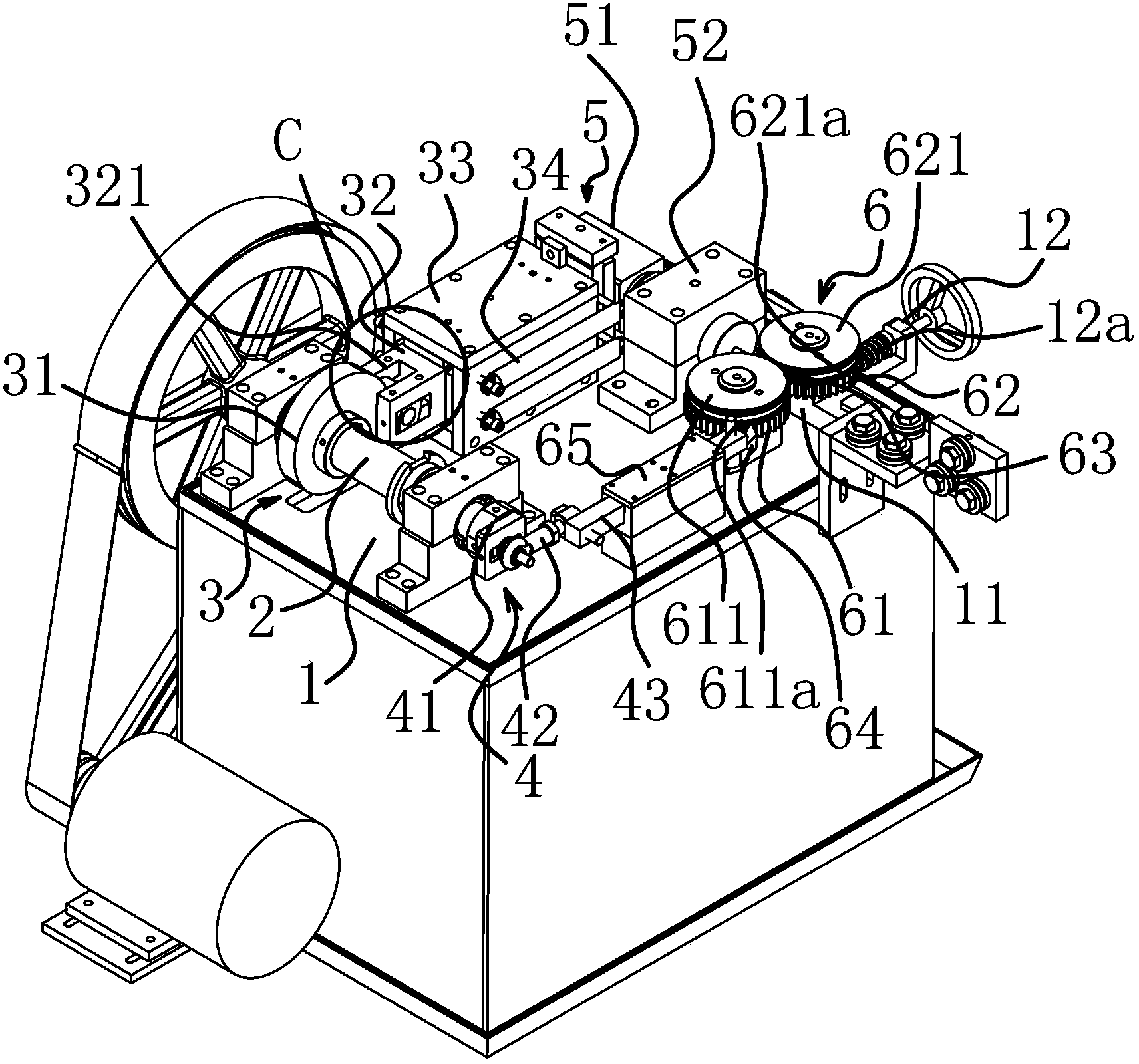
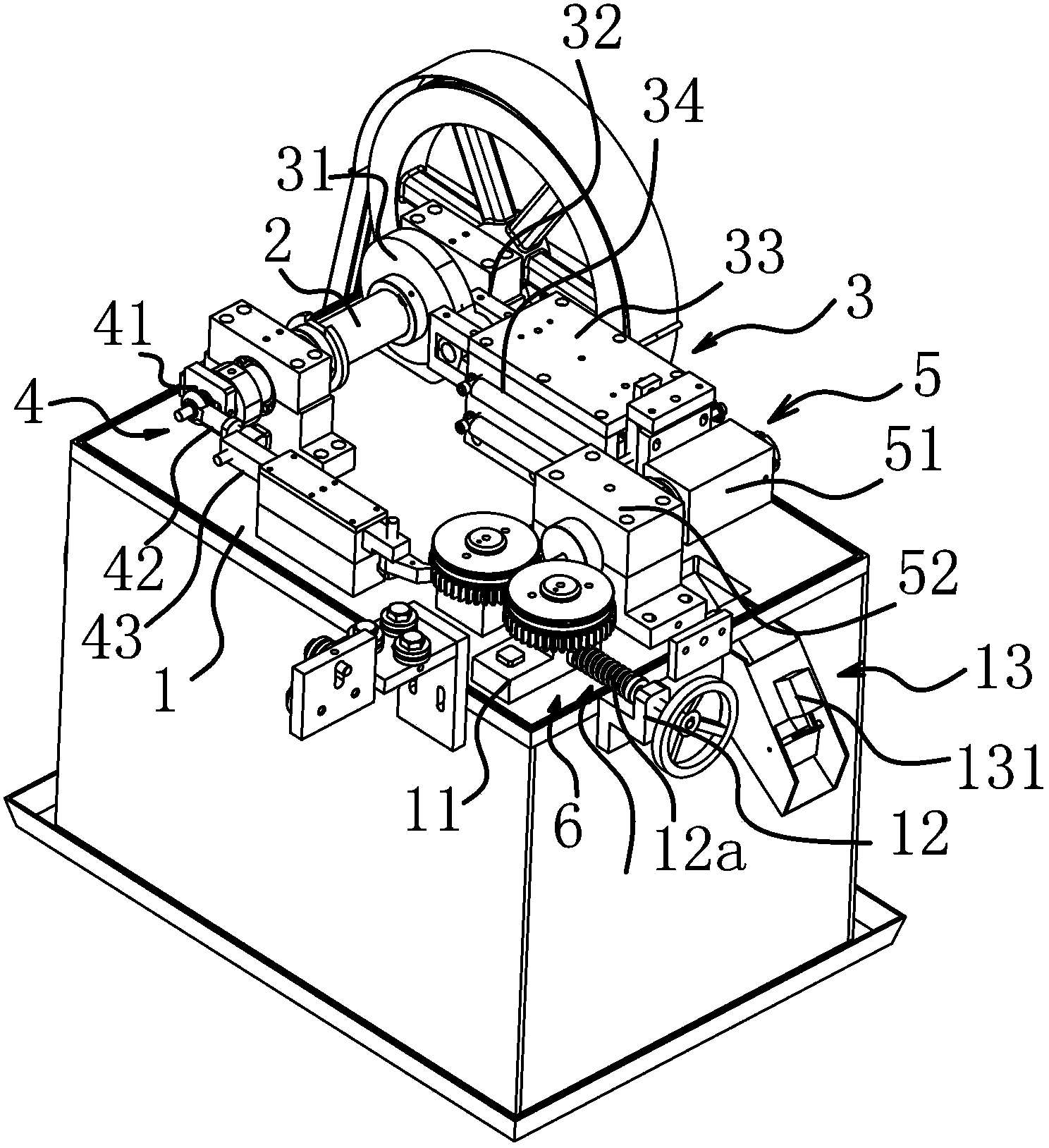
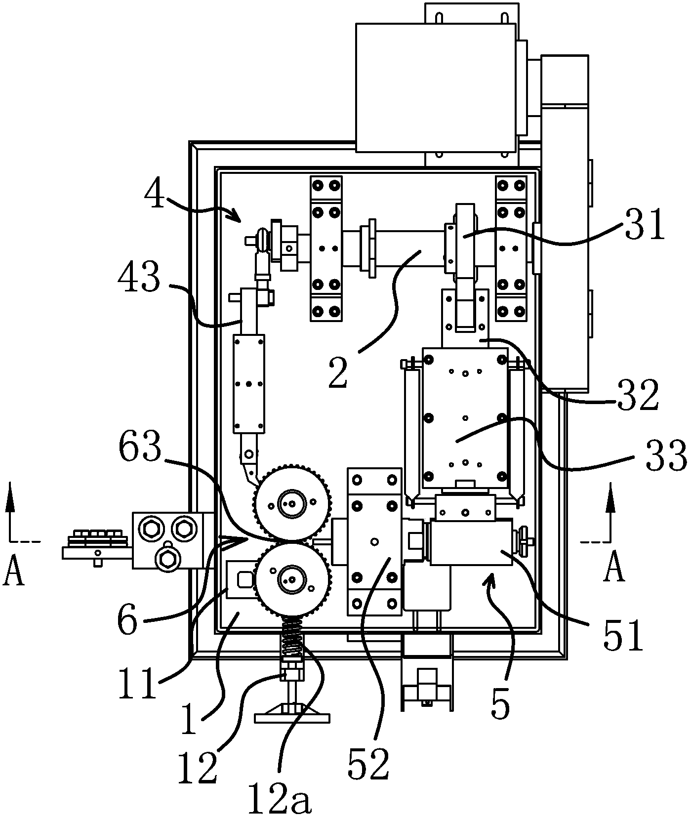
[0031] Such as Figure 1-6 As shown, the shaft pin machine includes a work platform 1. The work platform 1 is provided with a horizontally arranged and circumferentially rotatable drive shaft 2, and the drive shaft 2 is provided with a first drive assembly 3 distributed along the axis of the drive shaft 2. And the second drive assembly 4, the first drive assembly 3 is connected to the cutting mechanism 5 and can drive the cutting mechanism 5 to work, the second drive assembly 4 is connected to the feeding mechanism 6 and can drive the feeding mechanism 6 to work, and when the drive shaft 2 When rotating, the feeding mechanism 6 and the cutting mechanism 5 work alternately. The cutting mechanism 5 is located on one side of the feeding mechanism 6 and can receive the strip material input by the feeding mechanism 6 and cut the strip material into shaft pins.

[0032] The cutting mechanism 5 includes a fixed knife barrel assembly 51 and a movable knife barrel assembly 52 that are but...


PUM


Abstract

The invention belongs to the technical field of shaft pin manufacture, relates to shaft pin manufacture equipment, in particular to a chain pin shaft machine which solves the technical problems that the prior art is not reasonable enough, and the like. A drive shaft horizontally arranged and capable of rotating in the circumferential direction is arranged on a working platform; a first driving assembly and a second driving assembly distributed in the axial direction of the drive shaft are arranged on the drive shaft; the first driving assembly is connected with a truncating mechanism and can drive the truncating mechanism to operate; the second driving assembly is connected with a feeding mechanism and can drive the feeding mechanism to operate; when the drive shaft rotates, the feeding mechanism and the truncating mechanism can operate alternately; the truncating mechanism is positioned on one side of the feeding mechanism, and can receive stripe materials input by the feeding mechanism and truncate the stripe materials into pin shafts. Compared with the prior art, the pin shaft machine has the advantages as fellows: 1, the design is reasonable, the structure is simple, and the working efficiency is high; 2, the automation degree is high, and the labor intensity of workers is reduced.

Description

technical field [0001] The invention belongs to the technical field of shaft pin manufacturing, and relates to shaft pin manufacturing equipment, in particular to a shaft pin machine. Background technique [0002] Since my country's reform and opening up, the national economy has grown rapidly, and "scientific and technological innovation, independent innovation" has become the mainstream of domestic industrial development. my country's industry is gradually developing in the direction of intensive, energy-saving, emission-reducing, and low-carbon. In addition to being widely used in the chain industry, pin shafts are also widely used in industries such as bearings and universal joints. Therefore, higher technical requirements are put forward for the mechanical equipment for processing pin shafts. In the current technology, the shaft pin machine is noisy, backward in production, low in work efficiency, and product quality cannot be guaranteed. In addition, it is easy to pr...

Claims


Application Information

Patent Timeline
IPC IPC(8): B23P23/02
Inventor 袁柳杰郭锋孙丽燕
Owner ZHEJIANG HENGJIU MACHINERY GROUP ZHUJI SPECIAL CHAIN
Why Eureka
Try Eureka