
Insulation structure of wrench

An insulating structure and wrench technology, which is applied in the field of hand tools, can solve the problems that do not meet the needs of actual use, the trouble of repairing the internal components of the casing 11, and the time delaying the disassembly of the fasteners.

Inactive Publication Date: 2013-11-06
MATATAKITOYO TOOL
View PDF9 Cites 2 Cited by
  • Summary
  • Abstract
  • Description
  • Claims
  • Application Information

AI Technical Summary

Problems solved by technology

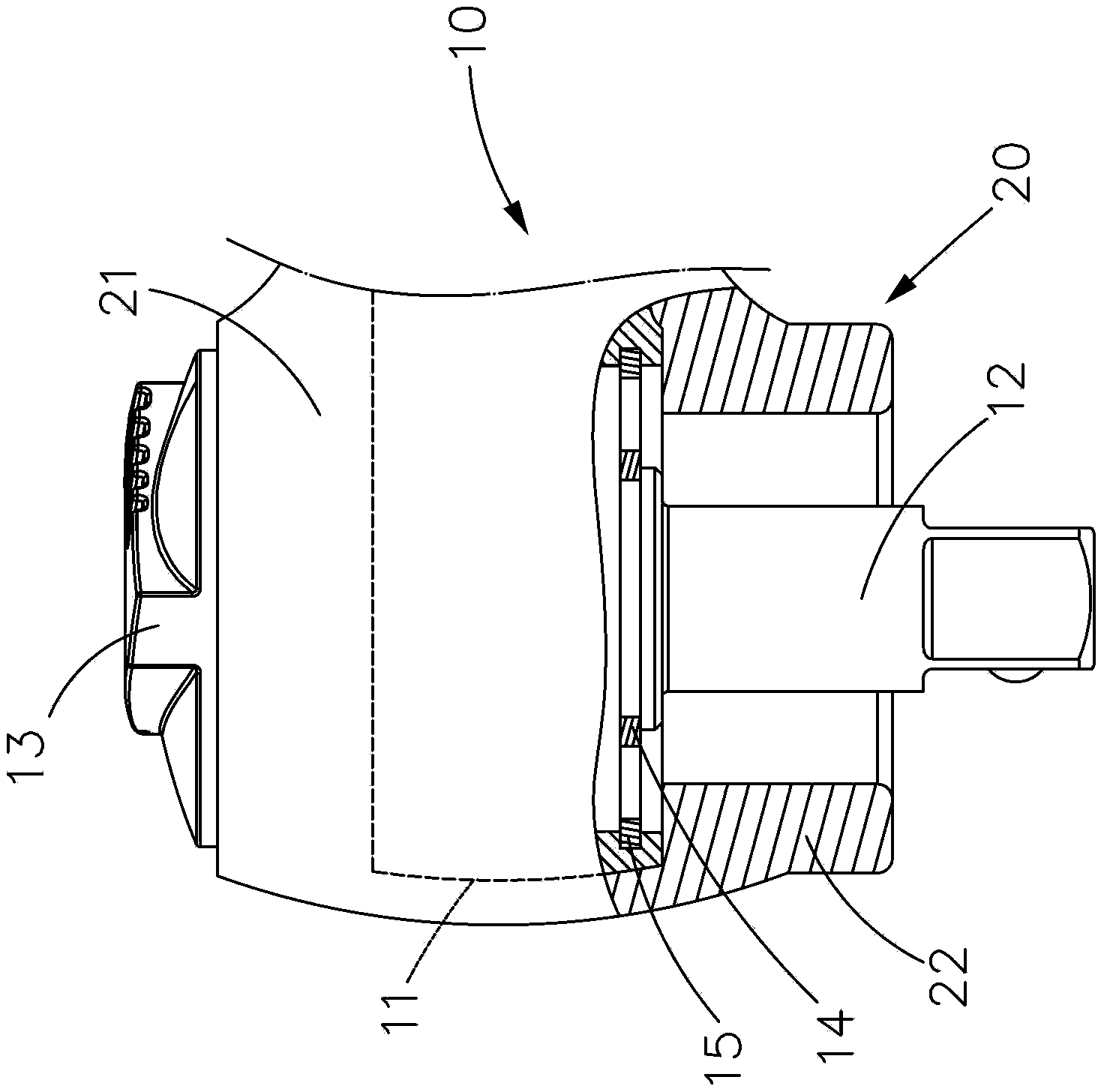
[0004] However, the diameter of the insulating cover part 22 is smaller than that of the housing 11. Although it will not hinder the removal of the first fastener 14 embedded in the insertion part 12, it will cover the wall of the housing 11 and embed a second fastener 15, delaying the buckle. The time to disassemble the parts, and there is no guarantee that they can be disassembled, causing troubles in the maintenance of the internal components of the housing 11
[0005] Moreover, the insulating cover part 22 cannot protect the insertion part 12, so that the user may accidentally touch the insertion part 12 during operation, thereby causing an accident of electric shock.
In addition, the wrench head 10 is not covered by the first and second fasteners 14, 15, so dust and foreign matter can easily enter the inside of the wrench head 10, forming a phenomenon of debris accumulation, which not only causes subsequent cleaning problems, but also easily causes wrench damage. Damage to the inside of the head 10 will shorten its service life
[0006] In other words, the existing insulated wrench has the problems of easy electric shock, difficult maintenance and easy chip damage, which does not meet the needs of actual use, and further technical development is needed to solve the aforementioned problems
[0007] In view of this, the designer of the present invention made in-depth discussions on the problems faced in the operation of the aforementioned existing wrenches, and actively sought solutions by virtue of years of experience in research and development and manufacturing in related industries. After continuous efforts in research and trial production , and finally successfully developed a wrench insulation structure to overcome the inconvenience and trouble caused by the existing ones due to difficult disassembly and insufficient protection

Method used


Image

  • Insulation structure of wrench
  • Insulation structure of wrench
  • Insulation structure of wrench

Examples


Embodiment Construction

[0023] The present invention is a wrench insulating structure. In the accompanying drawings illustrating specific embodiments of the present invention and its components, all references to front and rear, left and right, top and bottom, upper and lower, and horizontal and vertical are only It is used for convenience of description and does not limit the invention, nor its components, to any position or orientation in space. The dimensions specified in the drawings and description can be changed according to the design and requirements of the specific embodiments of the present invention without departing from the patent scope of the present invention.

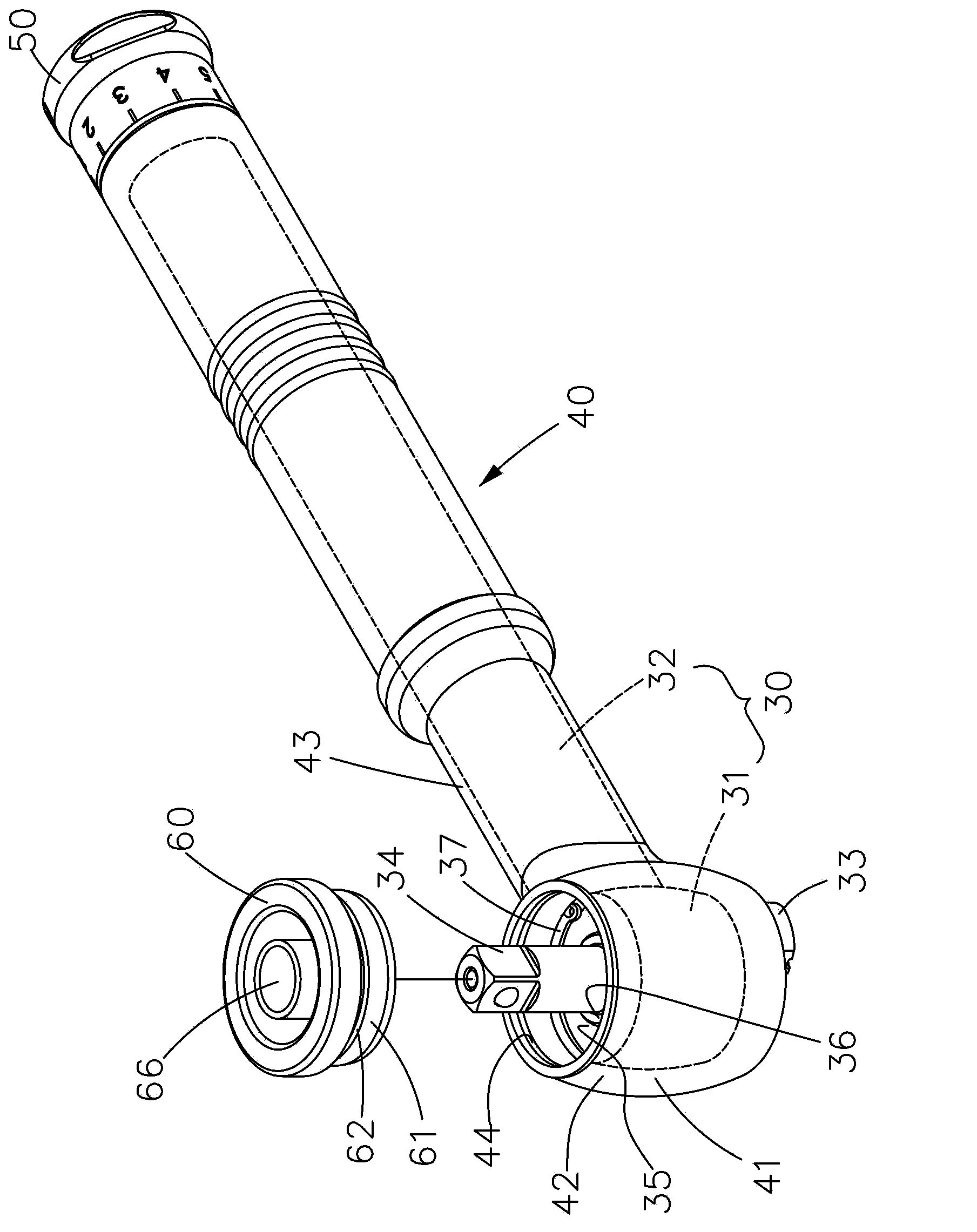
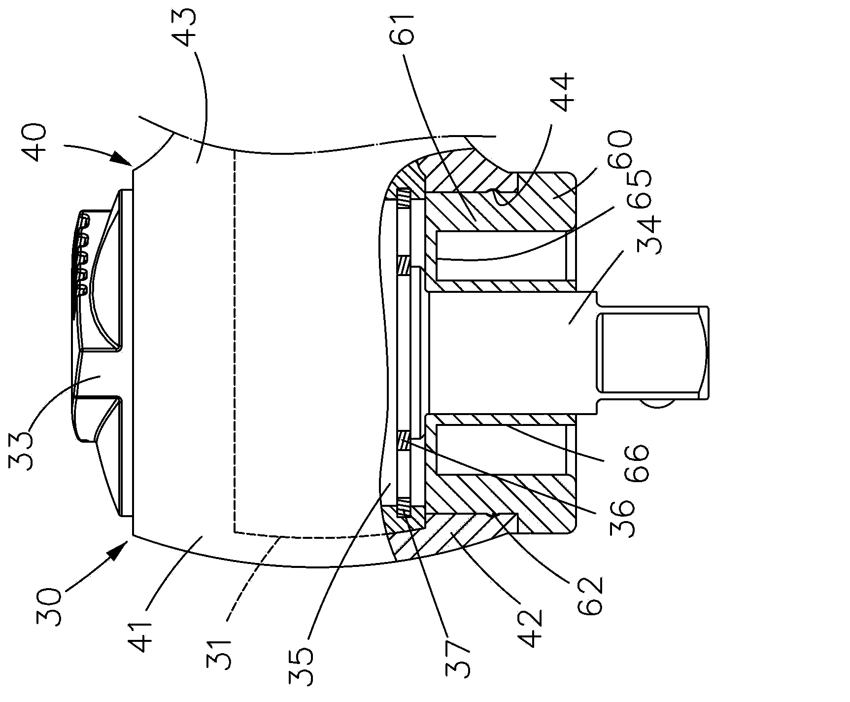
[0024] Wrench insulating structure of the present invention, as figure 2 , image 3 As shown, the wrench has a wrench head 30 with a drive assembly inside and a handle 32 integrally connected, wherein the handle 32 is locked into the end by an adjustment button 50, so that the handle 32 can be turned and applied force and pre...


PUM


Abstract

The invention relates to an insulation structure of wrench, specifically to an insulation structure of wrench with good protection effect. A wrench head of the wrench comprises a shell body; an insertion part is exposed on the outside of the shell body; an insulation layer comprises an insulation shell and an insulation sleeve part; while the insulation shell covers the outer surface of the shell body, the insulation sleeve part integrated with the insulation shell surrounds the insertion part; the insulation sleeve part is combined with an insulation loop; a combining section extends from the insulation loop along the inner wall of the insulation sleeve part; the insulation loop is provided with a connecting seal edge at the inner end of the combining section, the connecting seal edge converging towards the insertion part; and an insulation bush extends outward from the inner edge of the connecting seal edge in the axial direction of the outer wall of the insertion part. The insulation sleeve part is combined with the insulation loop, the insulation loop can be detached according to requirements for maintenance of the head of the insulation wrench and an insulation effect for preventing electric leakage is achieved.

Description

technical field [0001] The invention relates to the technical field of hand tools, in particular to a wrench insulation structure which has good insulation effect and can be repaired according to requirements, so as to improve the safety of operation. Background technique [0002] Generally, wrenches are used to fit screwed parts to release or lock screwed parts through forward and reverse methods. Therefore, there are many types of wrenches, from the simplest open-end wrench to ratchet wrench, and even torque wrench with controllable force. , and the working environment includes not only general workplaces, but also water areas and even electrical places. In terms of electrical occasions, since the wrench head and handle are used to pull the screw and apply force, under the consideration of strength, it is generally made of metal, and the metal wrench head and handle It is suitable as a conductive substance, and there is a danger of electric shock to the operation of perso...

Claims


Application Information

Patent Timeline
IPC IPC(8): B25B13/00B25B23/00
CPCB25G1/125B25B23/16B25B23/1427
Inventor 吴逸民
Owner MATATAKITOYO TOOL
Learn More