Axle counting system

A technology of axle counting and wheel sensors, which is applied in vehicle route interaction equipment, railway car body components, railway signals and safety, etc., can solve problems such as inability to indicate maintenance personnel, wheel sensors are easily interfered, and complex equipment, etc., to improve railway Operational efficiency and shortened maintenance time

Inactive Publication Date: 2013-11-06
SHENZHEN KEANDA ELECTRONICS TECH
View PDF5 Cites 2 Cited by
  • Summary
  • Abstract
  • Description
  • Claims
  • Application Information

AI Technical Summary

Problems solved by technology

At present, the axle counting system is widely used to detect the presence of trains on the rails. The axle counting system uses a magnetic head sensor to sense the signal of the train wheel. The sensor is divided into a sending part and a receiving part, which are installed on both sides of the rail. The receiving part checks that the magnetic field signal changes, and then transmits the detected signal to the axle counting host through the cable. The software in the host judges whether there is a train passing by through the signal waveform. The problem existing in the detection device in the existing axle counting system is : When railway construction personnel hold metal objects such as shovels across the magnetic field area of ​​the wheel sensor, it is easy to cause interference to the sensor to determine whether a train has passed. In addition, when the wheel sensor is loose from the installed rail, the axle counting equipment cannot check by itself If this kind of failure occurs, the maintenance personnel cannot be instructed to solve the failure in time, which will cause serious train safety accidents
[0003] In the prior art, in order to solve the problem that the wheel sensor is susceptible to interference, another strain sensor is installed on the rigid rail, such as the technical solution disclosed in ZL200820109965.4, which additionally adds a sensor and a device for processing the sensor signal, and the equipment complex and costly

Method used


Image

  • Axle counting system
  • Axle counting system
  • Axle counting system

Examples


Embodiment Construction

[0020] This embodiment is a preferred implementation mode of the present invention, and other principles and basic structures that are the same or similar to this embodiment are within the protection scope of the present invention.

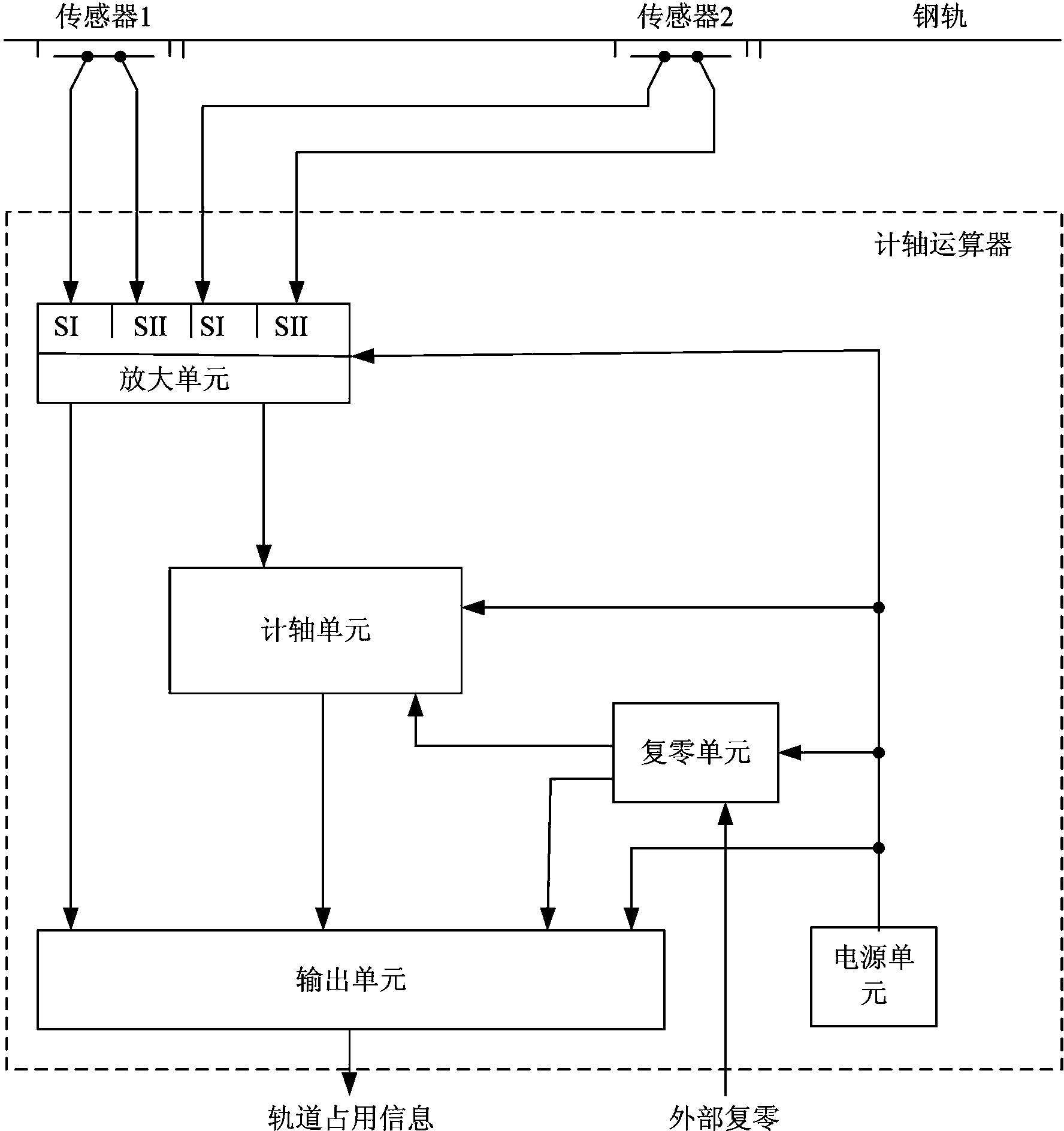
[0021] The axle counting system is used to check whether there is a train on the track. Specifically, the wheel sensor is used as the dividing point to divide the rail into sections. The track area formed between two wheel sensors is called a section. The axle counting system Compare the number of wheels entering the section with the number of wheels leaving the section. When the number of wheels entering is equal to the number of wheels leaving, it is determined that there is no train in the section, that is, the section is idle. When they are equal, it is determined that there is a train in the section, that is, the section is occupied.

[0022] The axle counting system of this embodiment includes a wheel sensor and an axle counting calculator. ...


PUM


Abstract

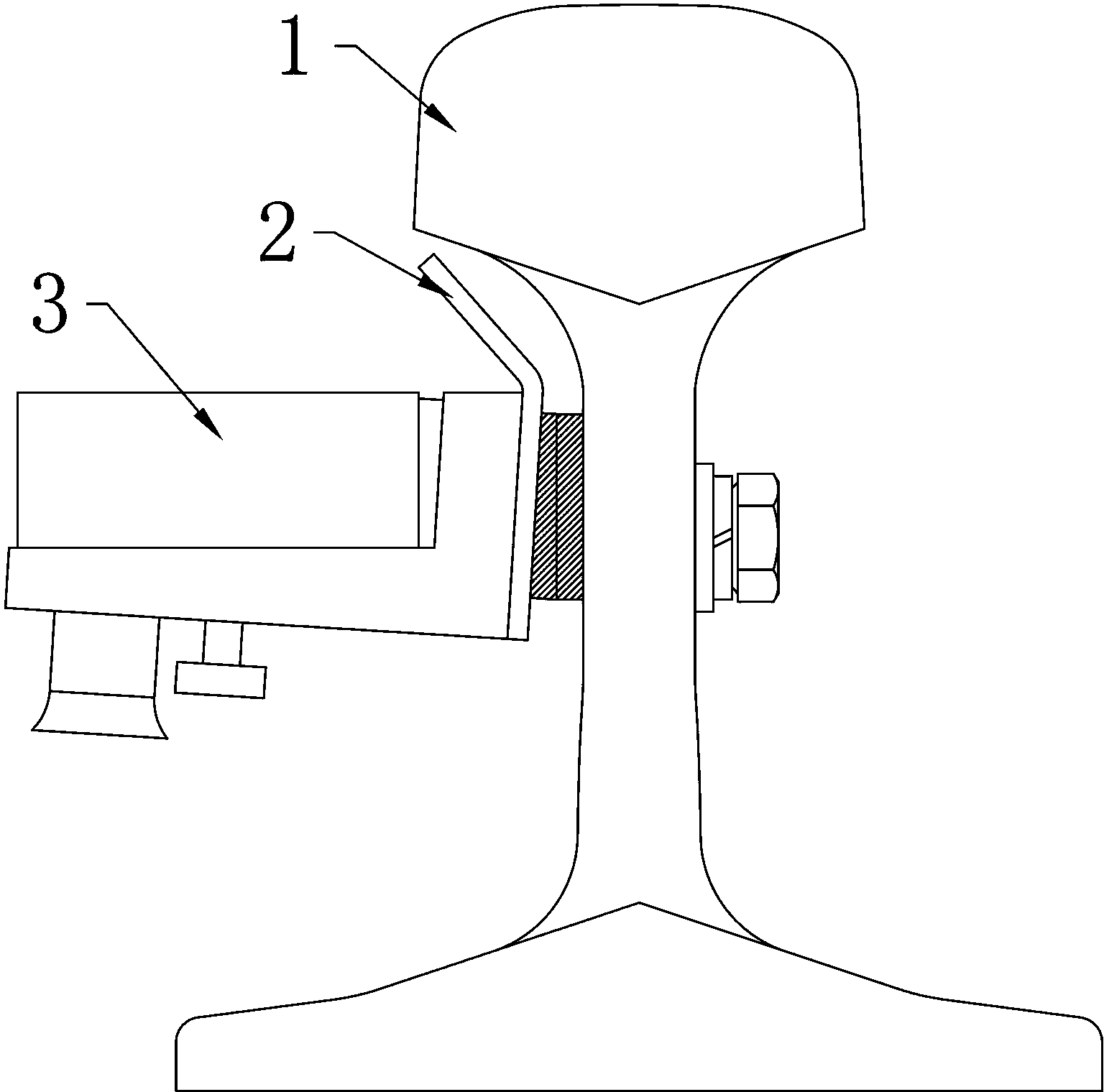
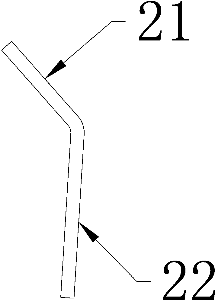
An axle counting system comprises a wheel sensor and an axle counting arithmetic unit. The wheel sensor is unilaterally installed on a steel rail, the top surface of the wheel sensor is lower than that of the steel rail, the axle counting arithmetic unit receives and operates signals, judges whether a rail section is occupied and outputs the signals. A damping board is further arranged between the wheel sensor and the steel rail. The axle counting arithmetic unit is provided with an amplifying unit, an axle counting unit and an output unit, wherein the amplifying unit processes the received signals and outputs the signals to the axle counting unit and the output unit, the axle counting unit recognizes the train traveling direction, calculates the number of wheels and transmits the results to the output unit, and the output unit outputs rail information. The wheel sensor is unilaterally installed on the steel rail, and the top surface of the wheel sensor is lower than that of the steel rail, so that the wheel sensor only has effect on rims of the train wheels lower than the top surface of the steel rail, and interference cannot be generated easily. The damping plate is further arranged between the sensor and the steel rail, when the wheel sensor is loose, alarm information can be emitted to remind maintain staff to repair timely, and operation safety is improved.

Description

technical field [0001] The invention discloses an axle counting system for detecting train wheels on rails. Background technique [0002] Railway transportation occupies a pivotal position in people's daily life and occupies a large proportion in the transportation industry. Since railway transportation belongs to rail transportation, due to its special operation mode, the requirements for its operating environment are also very high, and it is especially important that there can only be one train on the same section line at the same time. At present, the axle counting system is widely used to detect the presence of trains on the rails. The axle counting system uses a magnetic head sensor to sense the signal of the train wheel. The sensor is divided into a sending part and a receiving part, which are installed on both sides of the rail. The receiving part checks that the magnetic field signal changes, and then transmits the detected signal to the axle counting host thro...

Claims


Application Information

Patent Timeline
IPC IPC(8): B61L1/16
Inventor 张帆孙伟义梁伟全
Owner SHENZHEN KEANDA ELECTRONICS TECH
Why Eureka
Try Eureka