dual clutch device

A dual-clutch, single-clutch technology, applied in clutches, fluid-driven clutches, mechanically-driven clutches, etc., can solve the problems of lack of centrifugal oil cavity and inability to affect cooling oil flow, etc.

Active Publication Date: 2017-08-22
SCHAEFFLER TECH AG & CO KG
View PDF11 Cites 0 Cited by
  • Summary
  • Abstract
  • Description
  • Claims
  • Application Information

AI Technical Summary

Problems solved by technology

In addition to this, the above design lacks a centrifugal oil chamber for compensating the effect of the centrifugal force acting on the hydraulic medium when the masses in the hydraulic system are displaced
Although this is disclosed for example in EP0282169B or DE102004012948A1, even these designs have the disadvantage that the proportion of the cooling oil flow that should flow to the two single clutches cannot be influenced (that is, adjusted or controlled) during operation.

Method used


Image

  • dual clutch device
  • dual clutch device
  • dual clutch device

Examples


Embodiment Construction

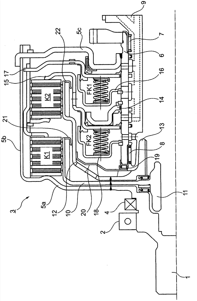
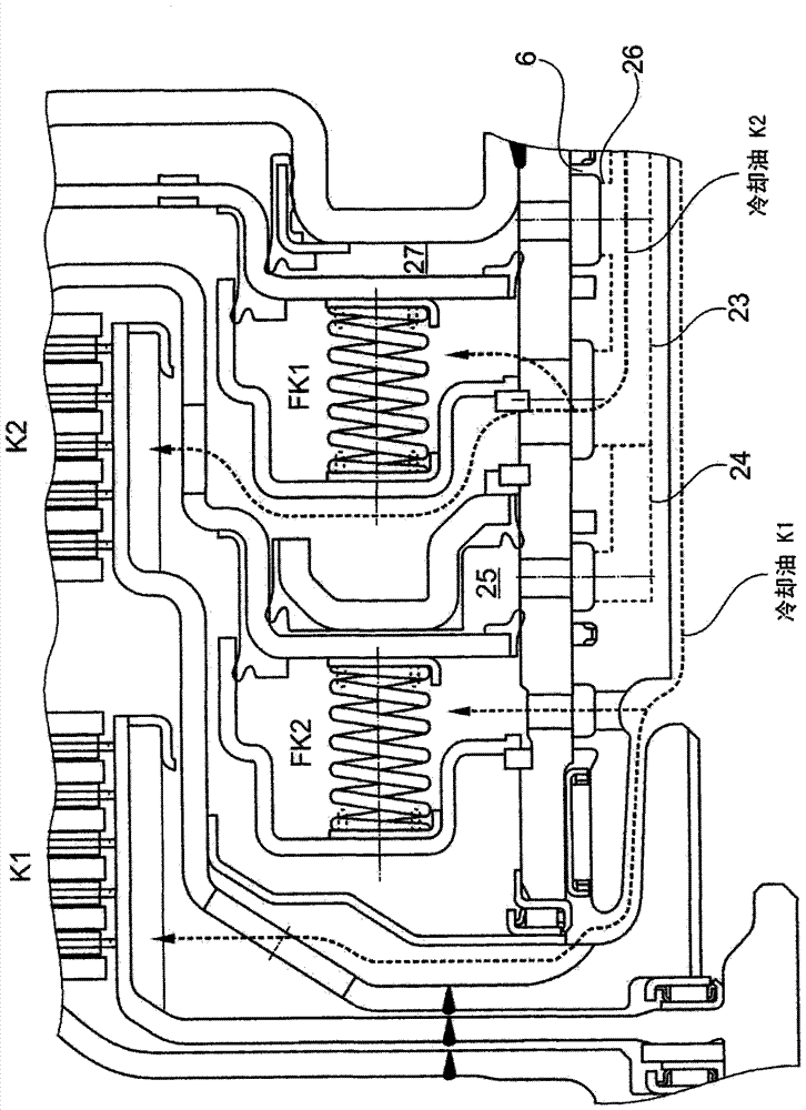
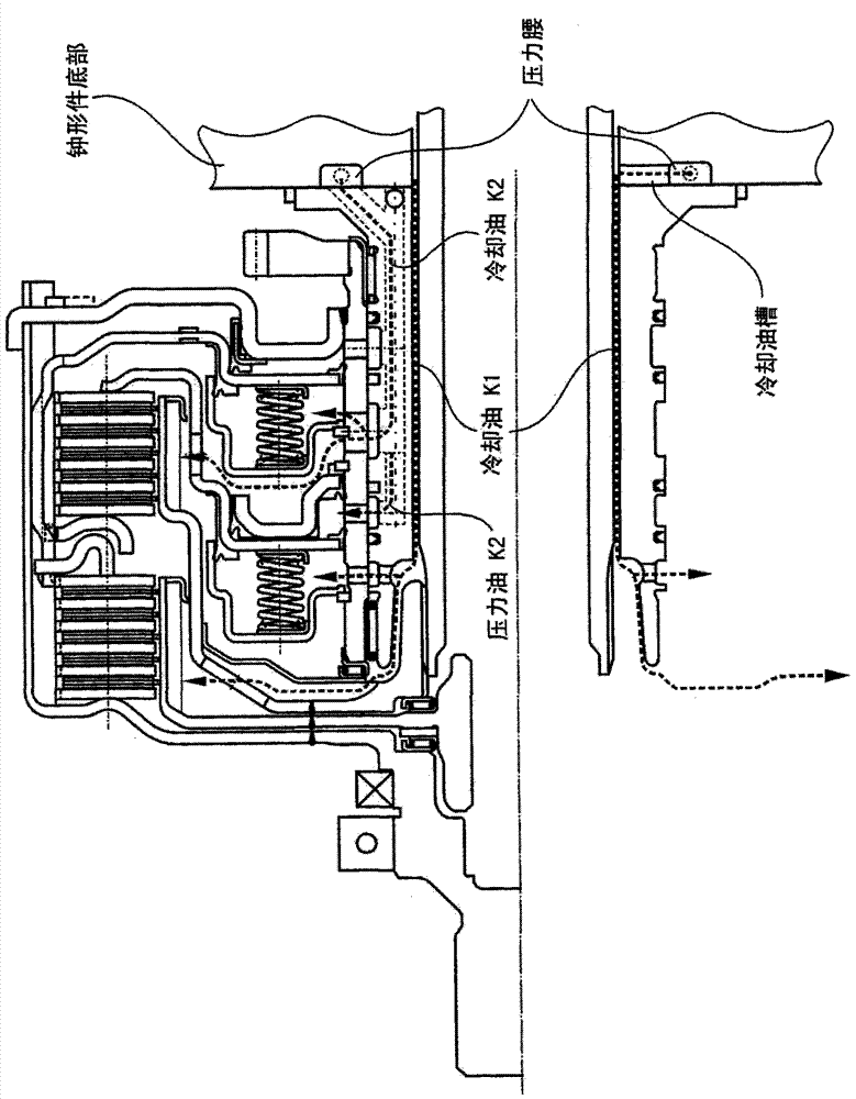
[0013] figure 1 A first exemplary embodiment of an axial wet dual clutch is shown, in which the torque from the drive motor is transmitted to the clutch hub, optionally via a torsional vibration damper, for example a dual mass flywheel (ZMS). The clutch hub 1 is supported on a ( figure 1 (not shown) housing that encloses a clutch bell in which the dual clutch assembly 3 is housed. The clutch bell, which accommodates the clutch 3 , is sealed from the environment by a sealing device 4 . The clutch bell is here generally formed by a recess (not shown separately) in the transmission housing. The clutch hub 1 is connected to a clutch housing 5 comprising a substantially radially extending entrainment region 5a and a substantially axially extending cylindrical region 5b with respect to the main axis of the dual clutch 3 and a radially extending connection - and the support area 5c. The connection and support region 5c is rotationally fixed and preferably also axially fixedly con...


PUM


Abstract

Wet double clutch, including a first single clutch and a second single clutch; including a clutch housing connectable to the driver and two piston-cylinder units, the clutch housing is connected to the input of the first transmission through the output friction plate carrier of the first single clutch The shaft is connected and connected to the input shaft of the second transmission through the output friction plate carrier of the second single clutch, the piston cylinder unit of the single clutch is arranged radially inside the friction plate pack of the single clutch and axially overlaps the friction plate pack at least partially The piston-cylinder unit of the single clutch has an operating piston, a pressure chamber and a centrifugal oil chamber respectively, and the clutch is supported on the transmission housing through the stator; it includes a first delivery device and a second delivery device hydraulically separated from the first delivery device , the first delivery device is used to simultaneously supply cooling oil to the centrifugal oil cavity of the second single clutch and the first single clutch, and the second delivery device is used to simultaneously supply cooling oil to the centrifugal oil cavity of the first single clutch and the second single clutch .

Description

technical field [0001] The invention relates to a wet dual clutch, comprising single clutches arranged axially one behind the other and hydraulically actuated for a dual clutch transmission in a drive train of a vehicle, comprising a first single clutch K1 axially arranged on the drive side and The second single clutch K2, arranged axially on the transmission side; comprises a clutch housing which can be connected to the drive and two piston-cylinder units, the clutch housing has a suspension area for the input disks of the two single clutches or is connected to the The suspension area connects the clutch housing to the first transmission input shaft via the output disk carrier of the first single clutch K1 which is arranged inside relative to the disk pack of the first single clutch K1 and via the second single clutch K2 The output friction plate carrier arranged inside relative to the plate set of the second single clutch K2 is connected to the input shaft of the second tran...

Claims


Application Information

Patent Timeline
Patent Type & Authority Patents(China)
IPC IPC(8): F16D25/10F16D25/0638
CPCF16D25/123F16D2021/0661F16D2021/0692F16D2300/0214F16D25/10F16D25/0638
Inventor J·阿诺尔德D·霍夫施泰特尔
Owner SCHAEFFLER TECH AG & CO KG
Why Eureka
Try Eureka