
Cable single twister allowing height and side-direction adjusting

A technology of height adjustment screw and single stranding machine, which is applied in the direction of textile cables, textiles and papermaking, cable/conductor manufacturing, etc. It can solve the problem that the height and side of the stranding mechanism cannot be adjusted, the cable cannot be used, and the work efficiency is low. Problems, to achieve the effect of increasing height adjustment and side adjustment functions, reducing damage, and strong applicability

Active Publication Date: 2013-11-06
ZHEJIANG SHIP ELECTRONICS TECH
View PDF7 Cites 4 Cited by
  • Summary
  • Abstract
  • Description
  • Claims
  • Application Information

AI Technical Summary

Problems solved by technology

[0002] Power cables and communication cables are the second pillar products of my country's export products. A large cable is twisted by multiple or pairs of small cables at a certain helical distance to improve the bending resistance of the cable and improve the electronic performance. The anti-interference ability of the signal, such as when two strands of cables need to be twisted, such a single-twisted machine is applied. The biggest shortcoming of the existing single-twisted machine is the height and side of the twisted wire mechanism. The directions cannot be adjusted, so it is difficult to ensure that the twisting mechanism and the take-up mechanism are at the same level, and the cables cannot be twisted normally, resulting in relatively low work efficiency and easy cable breakage. The stability is poor, it is easy to cause damage to the cable during the twisting process, and the processed cable cannot be used

Method used


Image

  • Cable single twister allowing height and side-direction adjusting
  • Cable single twister allowing height and side-direction adjusting
  • Cable single twister allowing height and side-direction adjusting

Examples


Embodiment Construction

[0020] The following are specific embodiments of the present invention and in conjunction with the accompanying drawings, the technical solutions of the present invention are further described, but the present invention is not limited to these embodiments.

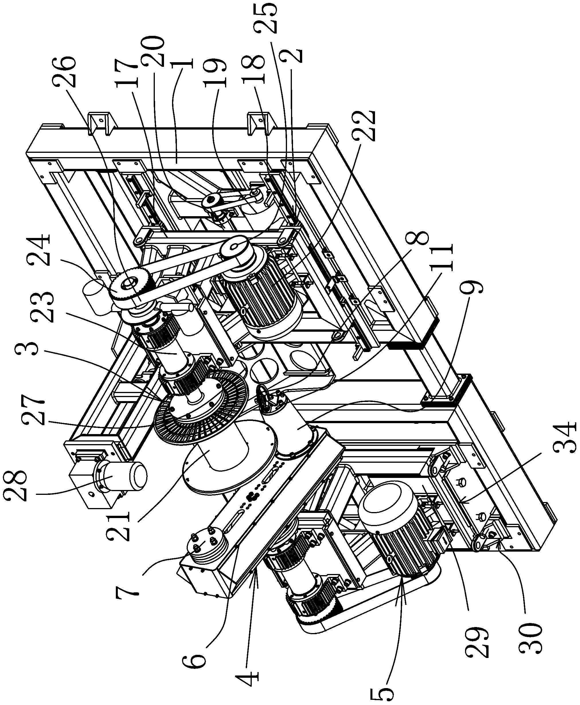
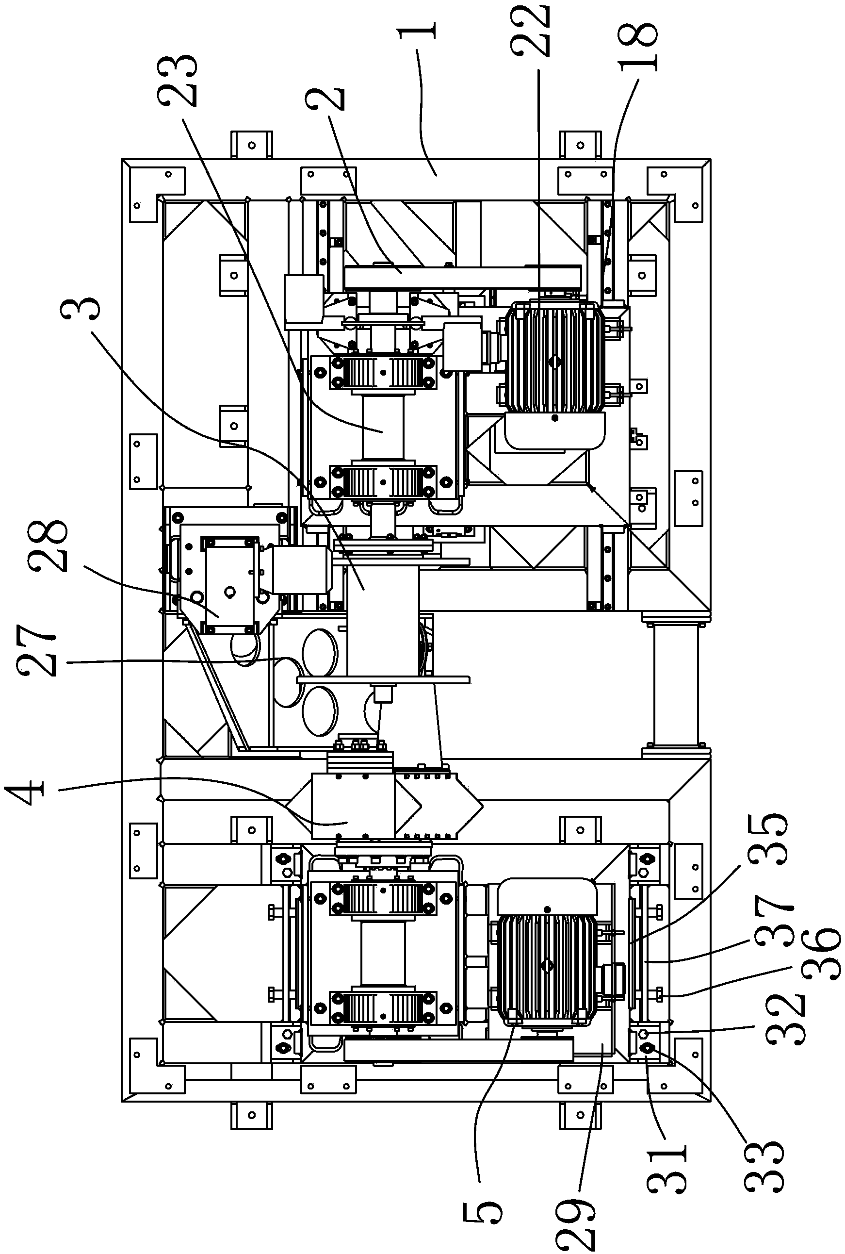
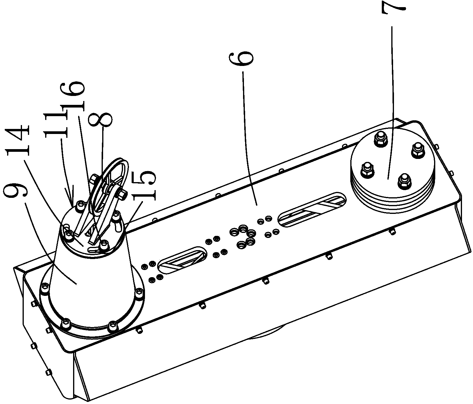
[0021] In the figure, the frame 1; the moving mechanism 2; the take-up mechanism 3; the twisting mechanism 4; the twisting driving mechanism 5; the twisting bow arm 6; the counterweight 7; ; the first guide wheel 12; the second guide wheel 13; adjusting disc body 14; adjusting slot 15; locking member 16; moving frame 17; moving guide rail 18; moving drive motor 19; Take-up drive motor 22; take-up rotating shaft 23; first pulley 24; second pulley 25; synchronous belt 26; rack 27; drive motor 28 for rack; Adjusting sheet 31 ; height adjusting screw 32 ; height locking screw 33 ; lateral distance adjusting part 34 ; top pressure plate 35 ; lateral adjusting screw 36 ; lateral fixing plate 37 .

[0022] Such as figure 1 as w...


PUM


Abstract

The invention belongs to the technical field of machines and provides a cable single twister allowing height and side-direction adjusting. The single twister comprises a machine base and a moving mechanism, a taking-up mechanism and a twisting mechanism which are arranged on the machine base, the taking-up mechanism and the moving mechanism are located on the right side of the machine base, the twisting mechanism is located on the left side of the machine base, the taking-up mechanism is located on the moving mechanism, the twisting mechanism comprises a twisting driving mechanism, a fixed plate is arranged on the lower portion of the twisting driving mechanism and on the machine base on the left side, the twisting driving mechanism is installed on the fixed plate, upper and lower height adjusting components are arranged between four corners of the fixed plate and the machine base, and side-direction distance adjusting components are arranged on upper and lower side portions of the fixed plate. The single twister has the advantages that height adjusting and side portion adjusting functions are added, so that the twisting mechanism and the taking-up mechanism are located on the same horizontal plane in all directions, the whole machine is stable and balanced during operation, and the performance of twisted lines is stable.

Description

technical field [0001] The invention belongs to the technical field of machinery, and relates to a cable or cable processing equipment, in particular to a cable single stranding machine with height and lateral adjustment. Background technique [0002] Power cables and communication cables are the second pillar products of my country's export products. A large cable is twisted by multiple or pairs of small cables at a certain helical distance to improve the bending resistance of the cable and improve the electronic performance. The anti-interference ability of the signal, such as when two strands of cables need to be twisted, such a single-twisted machine is applied. The biggest shortcoming of the existing single-twisted machine is the height and side of the twisted wire mechanism. The directions cannot be adjusted, so it is difficult to ensure that the twisting mechanism and the take-up mechanism are at the same level, and the cables cannot be twisted normally, resulting in re...

Claims


Application Information

Patent Timeline
Patent Type & Authority Applications(China)
IPC IPC(8): H01B13/02
CPCD07B3/085
Inventor 陈静竺永宏朱江南王廼宁马应科庄华盛
Owner ZHEJIANG SHIP ELECTRONICS TECH
Learn More