Automatic assembling device of fog lamp dimming ball component
An automatic assembly device and ball head technology, applied in assembly machines, metal processing equipment, manufacturing tools, etc., can solve the problems of unable to further improve production efficiency, unable to adjust the spring force, complex structure, etc., to shorten the auxiliary operation time, improve the Operational safety, effect of simplified structure
- Summary
- Abstract
- Description
- Claims
- Application Information
AI Technical Summary
Problems solved by technology
Method used
Image

Examples
Embodiment Construction
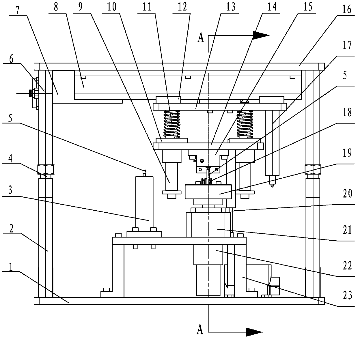
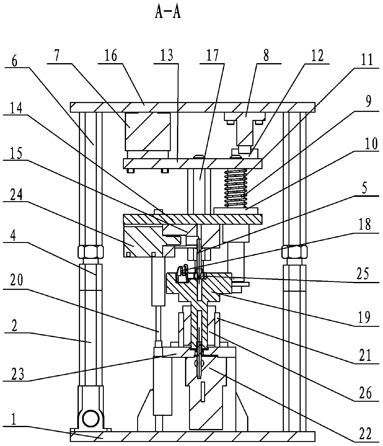
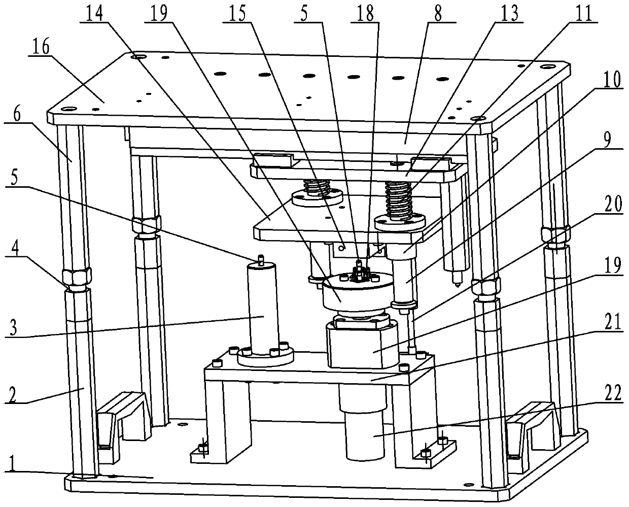
[0014] See Figure 1~3 As shown, the automatic assembly device of the fog lamp dimming ball head assembly of the present invention includes an upper mold assembly capable of moving up and down and a lower mold assembly installed on a workbench.
[0015] See Figure 1~3 As shown, the lower mold assembly of the present invention includes a bottom plate 1, at least four lower limit posts 2 installed on the bottom plate 1, a screw seat 3 installed on the bottom plate 1 through a bracket 23, and a ball head frame positioning and rotating mechanism, and the screw seat 3. Set the dimming screw hole. The bottom plate 1 of the present invention is installed on the workbench of the press through fasteners. The dimming screw 5 can be set in the dimming screw hole of the screw seat 3. light screw 5. See Figure 1~3 As shown, the ball head positioning and rotating mechanism of the present invention includes a motor 22, a support seat 21 and a rotating platform 19, and a bracket 23 is in...
PUM
 Abstract
Description
Claims
Application Information
PatSnap Eureka turns technology decisions into work you can execute. Powered by our Innovation Knowledge Graph, it runs expert workflows across engineering, life sciences, materials and intellectual property. Get your review-ready output in minutes.


