Automatic assembly device for fog lamp dimming ball assembly

An automatic assembly device and ball head technology, which is applied in the direction of assembly machines, metal processing equipment, manufacturing tools, etc., can solve the problems that the production efficiency cannot be further improved, the spring force cannot be adjusted, and the thread is damaged, so as to shorten the auxiliary operation time and improve Operational safety and the effect of ensuring assembly accuracy

Active Publication Date: 2016-03-23
CHANGZHOU XINGYU AUTOMOTIVE LIGHTING SYST CO LTD
View PDF7 Cites 0 Cited by
  • Summary
  • Abstract
  • Description
  • Claims
  • Application Information

AI Technical Summary

Problems solved by technology

However, in the automatic assembly device with the above structure, the pressure head and the screw pick-up mechanism need to be connected with their respective cylinders, which not only has a complex structure, but also the pressure head and the screw pick-up mechanism are operated separately, which cannot further improve production efficiency.
Furthermore, the rotating disk of the nut seat mechanism is provided with a guide rod, and the guide rod is supported by a spring, and the ball head hole is limited by the guide rod, but the elastic force of the spring cannot be adjusted due to the limitation of the assembly space. After the reduction, when the guide rod cannot position the dimming nut, and the dimming nut and the dimming screw are randomly placed, the resistance suddenly increases when the screw and the ball head are in contact with each other for a moment, which will cause damage to the thread

Method used


Image

  • Automatic assembly device for fog lamp dimming ball assembly
  • Automatic assembly device for fog lamp dimming ball assembly
  • Automatic assembly device for fog lamp dimming ball assembly

Examples


Embodiment Construction

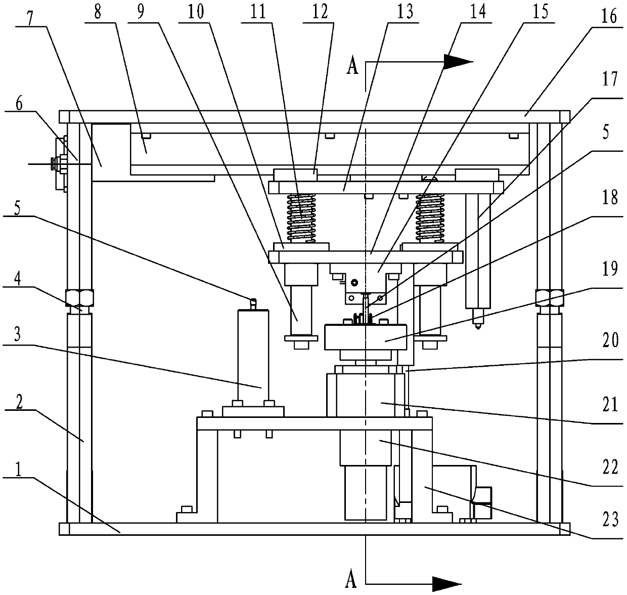
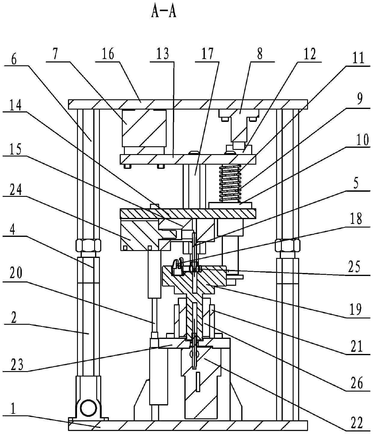
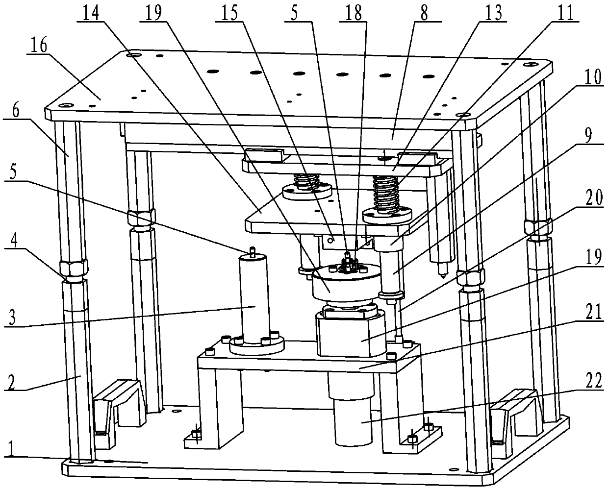
[0014] See Figure 1~3 As shown, the automatic assembly device of the fog lamp dimming ball head assembly of the present invention includes an upper mold assembly capable of moving up and down and a lower mold assembly installed on a workbench.

[0015] See Figure 1~3 As shown, the lower mold assembly of the present invention includes a bottom plate 1, at least four lower limit posts 2 installed on the bottom plate 1, a screw seat 3 installed on the bottom plate 1 through a bracket 23, and a ball head frame positioning and rotating mechanism, and the screw seat 3. Set the dimming screw hole. The bottom plate 1 of the present invention is installed on the workbench of the press through fasteners. The dimming screw 5 can be set in the dimming screw hole of the screw seat 3. light screw 5. See Figure 1~3 As shown, the ball head positioning and rotating mechanism of the present invention includes a motor 22, a support seat 21 and a rotating platform 19, and a bracket 23 is in...


PUM


Abstract

The invention relates to an automatic assembling device of a fog lamp dimming ball component. A lower die component comprises a bottom plate, a lower limiting column, and a screw base and a ball frame positioning and rotating mechanism which are installed on the bottom plate through a bracket, wherein the ball frame positioning and rotating mechanism comprises a motor, a supporting base and a rotating platform; an upper component comprises an upper limiting column, a lateral moving mechanism and a hold-down mechanism, wherein the lateral moving mechanism comprises a lateral cylinder and a guide rail which are installed on a top plate; the lateral cylinder and a sliding plate are arranged on the guide rail; the hold-down mechanism comprises a ball pressing rod and a screw picking and clamping mechanism; a guide column of the screw picking and clamping mechanism and the ball pressing rod are installed on the sliding plate; a guide sleeve is installed on a corresponding guide column and connected with a moving plate; a spring is sleeved on the guide column and positioned at the upper part of the guide sleeve; a grabbing cylinder is installed on one side of a grabbing base connected with the moving plate; and a displacement sensing mechanism is installed on the screw picking and clamping mechanism of the upper die component or / and the lower die component. The automatic assembling device simplifies the structure, and can further improve the assembly efficiency.

Description

technical field [0001] The invention relates to an automatic assembly device for a fog lamp dimming ball head assembly, which belongs to the technical field of motor vehicle lamp processing. Background technique [0002] Fog lights of motor vehicles need to be dimmed using a flexible and convenient ball head dimming mechanism. The dimming mechanism is composed of a dimming screw, a ball head and a ball head frame. The outer circumference of the ball head is spherical and has a threaded hole inside. The shaft of the dimming screw is circular, and the ball head is installed on the spherical surface of the ball head frame. Inside, the dimming screw is screwed on the ball head and connected with the connecting piece in the lamp, and the purpose of dimming is achieved by rotating the dimming screw. In the assembly process of the conventional ball head dimming mechanism, usually the dimming screw is screwed onto the ball head first, and then the ball head is pressed into the ball...

Claims


Application Information

Patent Timeline
Patent Type & Authority Patents(China)
IPC IPC(8): B23P21/00
Inventor 施玉峰刘秋鹏陈智
Owner CHANGZHOU XINGYU AUTOMOTIVE LIGHTING SYST CO LTD
Why Eureka
Try Eureka