Magnesium metal smelting reducing furnace material loading apparatus
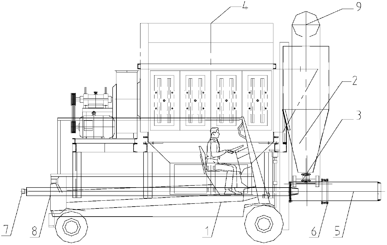
A reduction furnace and metal magnesium technology are applied in that the conversion joint 7 is located at the front end of the compressed air flexible pipe 8. The solution is: the present invention relates to a metal magnesium, a metal magnesium smelting reduction furnace charge charging equipment, a horizontal metal In the field of charging equipment for magnesium smelting reduction furnaces, it can solve the problems of increasing the number of labor and labor, increasing production costs, and increasing the ratio of magnesium in a single tank, and achieve the effect of reducing the number of labor and labor, reducing production costs, and reducing the ratio of material to magnesium.
- Summary
- Abstract
- Description
- Claims
- Application Information
AI Technical Summary
Problems solved by technology
Method used
Image
Examples
Embodiment 1
[0012] The main components and component parameters of Example 1:
[0013] The invention relates to a horizontal metal magnesium smelting reduction furnace charge loading equipment, including a forklift 1, a hopper 2, a pneumatic discharge valve 3, a small bag-type pulse dust collector 4, a material and airflow pipeline 5, a sealing flange 6, a Compressed air quick changeover joint 7, compressed air flexible pipe 8, and dust removal pipe 9, which is characterized in that a metal magnesium smelting reduction furnace charge charging equipment is connected to external compressed air through a compressed air quick changeover joint 7 to reduce furnace charge Furnace installed. The forklift 1 is used to install all components. The hopper 2 is used for loading the reduction furnace charge. The pneumatic discharge valve 3 is used to open and close the discharge port of the material hopper 2. The small bag-type pulse dust collector 4 is used to collect and process the dust generated ...
Embodiment 2
[0014] Example 2 work process:
[0015] Connect the compressed air quick changeover joint 7 on the compressed air flexible pipe 8 with the compressed air pipe or the outlet pipe of the gas storage tank at the site. The forklift 1 drives to the reduction furnace, aligns the reduction tank, and extends the compressed air quick changeover joint 7 into In the reduction tank, ensure that the sealing flange 6 is in close contact with the opening of the reduction tank. After opening the control valve of the on-site compressed air pipeline for 2-3 seconds, open the pneumatic discharge valve 3 under the hopper 2, so that the material falling and the large flow of compressed air in the air flow pipeline 5 are transported to the reduction tank.
PUM
 Abstract
Description
Claims
Application Information
 - R&D
- Intellectual Property
- Life Sciences
- Materials
- Tech Scout
- Unparalleled Data Quality
- Higher Quality Content
- 60% Fewer Hallucinations
Browse by: Latest US Patents, China's latest patents, Technical Efficacy Thesaurus, Application Domain, Technology Topic, Popular Technical Reports.
© 2025 PatSnap. All rights reserved.Legal|Privacy policy|Modern Slavery Act Transparency Statement|Sitemap|About US| Contact US: help@patsnap.com

