Magnetic sensor

A technology of magnetic sensors and magnetoresistive effect elements, applied in the field of magnetic sensors, can solve problems such as difficulty in obtaining sensor characteristics, complicated manufacturing process, and rising manufacturing costs, and achieve the goals of easy manufacturing process, high-precision sensor characteristics, and reduced manufacturing costs Effect

Active Publication Date: 2013-11-13
ALPS ALPINE CO LTD
View PDF8 Cites 9 Cited by
  • Summary
  • Abstract
  • Description
  • Claims
  • Application Information

AI Technical Summary

Problems solved by technology

That is, in the case of using a conductor portion for resistance adjustment for a magnetic sensor provided with serpentine elements in different extending directions, it is not possible to use a single conductor portion, so it is necessary to manufacture a conductor suitable for each serpentine element. department
[0005] In this way, in the prior art

Method used


Image

  • Magnetic sensor
  • Magnetic sensor
  • Magnetic sensor

Examples


Embodiment Construction

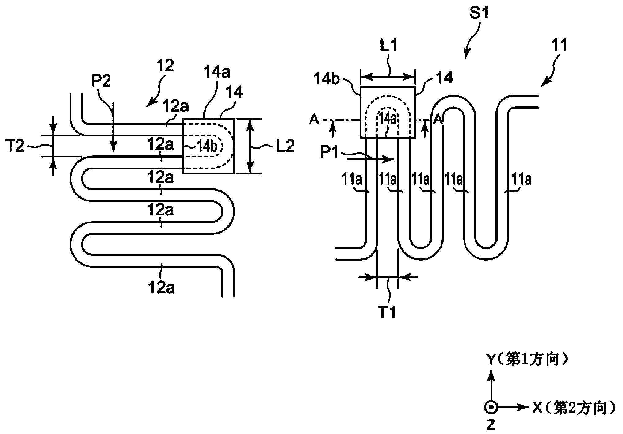
[0037] figure 1 It is a plan view showing an example of a first element and a second element mounted in the magnetic sensor of the first embodiment.

[0038] here, in figure 1 In the first embodiment shown, the Y direction is defined as a first direction, and the X direction perpendicular to the Y direction is defined as a second direction. The X direction and the Y direction represent two directions orthogonal to each other in a plane. On the other hand, the Z direction represents a height direction (thickness direction) perpendicular to both of the X direction and the Y direction.

[0039] In the magnetic sensor S1, a plurality of meander elements 11, 12 are formed on the same substrate.

[0040] The meander element 11 is a first element, and is sometimes referred to as a first element 11 hereinafter. In addition, the meander element 12 is a second element, and may be referred to as a second element 12 hereinafter.

[0041] Such as figure 1 As shown, the first element ...


PUM


Abstract

The invention aims to provide a magnetic sensor which only uses one pattern of conductor parts relative to plural winding components different in extension direction of extension parts. A first component (11) extends in the Y direction and is a winding component formed by connecting plural first extension parts (11a) arranged at intervals in the X direction, and a second component (12) extends in the X direction and is a winding component formed by connecting plural second extension parts (12a) arranged at intervals in the Y direction. At least one of the first component and the second component is a magnetoresistive effect component of exerting the magnetoresistive effect. Conductor parts (14) are connected between the first extension parts (11a) or the second extension parts (12a) arranged at intervals and are squares having first edges (14a) extending in the X direction and second edges (14b) in the Y direction. The lengths (L1) of the first edges are longer than intervals (T1), and the lengths (L2) of the second edges are longer than intervals (T2).

Description

technical field [0001] The present invention relates to a magnetic sensor including a plurality of meander elements extending in different directions and a conductor portion for adjusting resistance. Background technique [0002] Patent Document 1 discloses an invention related to a hybrid circuit device. Although Patent Document 1 is not an invention related to a magnetic sensor, Patent Document 1 discloses a configuration in which resistance adjustment of a meandering element is short-circuited between resistance layers of a meandering element using a meandering loop (conductor portion). [0003] On the other hand, Patent Document 2 discloses an invention related to an AMR sensor element for angle measurement. For example, in Patent Document 2 figure 1 Two Wheatstone bridges 11 and 12 are provided in the circuit, and each Wheatstone bridge is composed of four meandering resistors 13 . The extending directions of the four meandering resistors 13 (directions in which the ...

Claims


Application Information

Patent Timeline
IPC IPC(8): G01D5/16G01R33/09
Inventor 小池文人佐佐木晋一远藤一一朝妻浩太
Owner ALPS ALPINE CO LTD
Why Eureka
Try Eureka