
Design method for vibration isolation system in central air conditioner room

A technology of central air-conditioning machine room and vibration isolation system, applied in computing, special data processing applications, instruments, etc., can solve the problems of blind vibration isolation design, incapable of vibration isolation design, not intuitive enough, etc., and achieve the effect of intuitive vibration isolation design

Active Publication Date: 2013-11-13
宁波坤博测控科技有限公司
View PDF0 Cites 17 Cited by
  • Summary
  • Abstract
  • Description
  • Claims
  • Application Information

AI Technical Summary

Problems solved by technology

[0003] The purpose of the present invention is to overcome the large uncertainty in the vibration isolation design of a single device in the prior art, and the traditional vibration isolation design is blind and not intuitive enough to isolate multiple devices in the central air-conditioning machine room. Based on the deficiencies of vibration design, a new design method of vibration isolation system based on power flow analysis is proposed

Method used


Image

  • Design method for vibration isolation system in central air conditioner room
  • Design method for vibration isolation system in central air conditioner room
  • Design method for vibration isolation system in central air conditioner room

Examples


Embodiment Construction

[0033] Further describe content of the present invention below in conjunction with accompanying drawing and embodiment of description:

[0034] 1. The vibration isolation system model of the heat pump unit in the central air-conditioning room

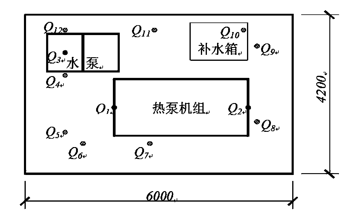
[0035] figure 1 It is a diagram of the equipment layout and measuring points of a central air-conditioning machine room. The machine room includes heat pump units, water pump units, pipelines, desanders, water collectors, water separators and other auxiliary equipment. The size of the machine room is 6m long, 4.2m wide, and 2.7m high m. Among them, the heat pump unit, water pump unit and pipeline in the machine room are the main equipment that generate vibration.

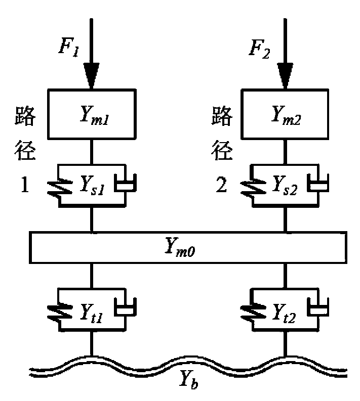
[0036] figure 2 It is a dual-excitation and dual-output secondary vibration isolation system model established according to the equipment type of the heat pump unit. Such as figure 2 As shown, the two excitations are F 1 and F 2 , each stimulus is equivalent in theor...


PUM


Abstract

The invention relates to a design method for a vibration isolation system in a central air conditioner room. The design method comprises the steps of establishing a power flow vibration isolation model according to major equipment in the central air conditioner room, drawing relation curves between structural parameters of the vibration isolation structure and transmitted power flow, vibrating speed and transmitted load, and determining the structural parameters of the vibration isolation system in the room; actually measuring data of vibration and noise in the central air conditioner room, establishing a vibration-sound coupling sound field finite element model, analyzing a mutual coupling relation between vibration and noise, and analyzing the effect degree of each piece of equipment in the central air conditioner room to the vibration-sound field; and under the condition of the mutual effect of the vibration-sound field, determining vibration isolation targets and a vibration isolation and noise reduction frequency band in the central air conditioner room by taking energy as an evaluation index, drawing the power flow transmission curve of the vibration isolation system and optimizing the structural parameters of a vibration isolator. Since the central air conditioner room is viewed as a large system, the influence relation between the vibration and the noise of each piece of equipment in the room is clear and the vibration of facilities is guaranteed to satisfy the standard; and since the energy is used as a vibration reduction index, the vibration isolation design is enabled to be more intuitive.

Description

technical field [0001] The invention relates to a design method of a vibration isolation system, in particular to a design method of a vibration isolation system of a central air-conditioning machine room based on power flow analysis. Background technique [0002] my country has successively promulgated a number of vibration isolation technical specifications, but these specifications are aimed at individual spaces and single equipment, with a single parameter such as force, velocity, and displacement transmission rate as the evaluation index of the vibration isolation system. The vibration level drop standard is used to design the vibration isolation device. However, in the actual central air-conditioning system engineering, many kinds of equipment are collected in the machine room. Since there are many vibration sources, and the equipment is connected by pipes and other accessories, the isolated vibration isolation design for a single equipment cannot make the whole system ...

Claims


Application Information

Patent Timeline
IPC IPC(8): G06F17/50
Inventor 陈长征费朝阳周勃勾轶
Owner 宁波坤博测控科技有限公司
Learn More